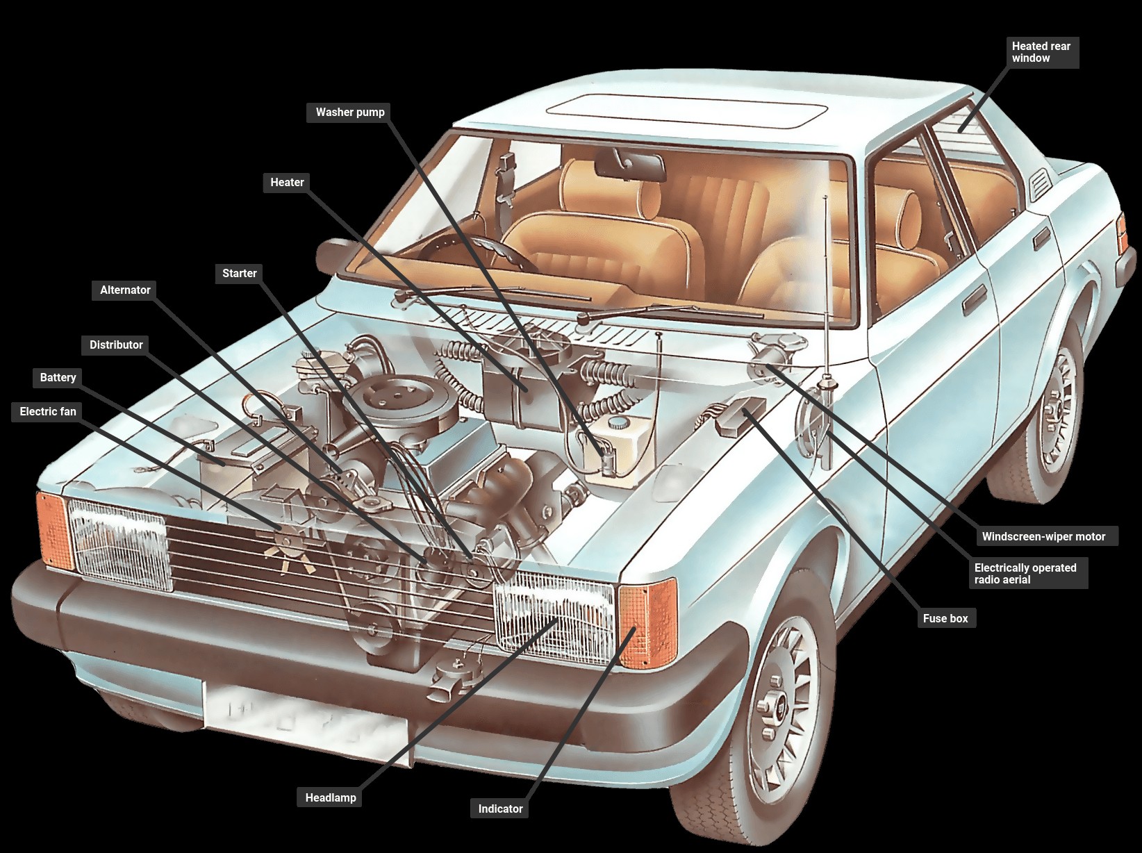
The unsung hero powering every modern vehicle is its Car Electric Wiring system. Far more intricate than the simple circuits of older models, today’s automotive electrical systems manage everything from starting the engine to running sophisticated infotainment and safety features. Understanding the basics of car electric wiring is becoming increasingly crucial for car owners and enthusiasts alike.
At its core, a car electric wiring system is a closed circuit fueled by the car battery, an independent power source. Unlike household circuits operating at high voltage, your car’s system functions on a much lower voltage, typically 12 volts. This carefully orchestrated network powers a vast array of components, moving beyond just the essential circuits for charging, starting, and ignition. Modern car electric wiring systems also energize lights, electric motors, instrument sensors and gauges, heating elements, electronic locking mechanisms, and entertainment systems. These diverse circuits are meticulously controlled by switches and relays, the latter acting as remote switches activated by electromagnets, ensuring efficient and safe power distribution throughout your vehicle’s electrical network. Current flows from the battery via dedicated wires to each component and returns to the battery through the car’s metal body, which acts as a conductor. A substantial cable firmly connects the car’s body to the battery’s earth terminal, completing this vital circuit.
The Earth-Return System in Car Electric Wiring
The car electric wiring system commonly employs a negative earth-return system. In this setup, the electric current travels from the positive (+) battery terminal to the component in operation. Crucially, the component is then “earthed” or grounded to the car’s metal body. This body, in turn, is connected back to the negative (-) terminal of the battery. This design is termed an earth-return system, where any part connected to the car body is considered earthed.
The flow of electricity within car electric wiring is characterized by two primary measurements: amperage and voltage. Amperage (amps) quantifies the strength of the electric current, while voltage (volts) represents the electrical pressure propelling the current through the circuit. Most contemporary vehicles utilize a 12-volt battery. Battery capacity is measured in amp-hours (Ah), indicating its ability to deliver current over time. For example, a 56 amp-hour battery should theoretically supply 1 amp for 56 hours or 2 amps for 28 hours. A drop in battery voltage directly impacts current flow, potentially reducing it to a level insufficient for proper component operation, highlighting the importance of maintaining optimal battery health for your car electric wiring system.
Understanding Current, Voltage, and Resistance in Car Electric Wiring
Resistance, measured in ohms, is a fundamental concept in car electric wiring, describing the degree to which a wire impedes the flow of electric current. Thicker wires offer less resistance because they provide a larger pathway for electrons to move through compared to thinner wires. As current is forced through resistance, electrical energy is converted into heat. This principle is intentionally used in components like light bulb filaments, where extreme heat generates light. However, in car electric wiring, excessive resistance can be problematic. Components with high current demands require appropriately thick wires. Using wires that are too thin can lead to overheating, potentially blowing fuses or causing wire burnout, emphasizing the need for correct wire gauge selection in car electric wiring.
The relationship between voltage, current, and resistance is defined by Ohm’s Law: Voltage (Volts) divided by Resistance (Ohms) equals Current (Amps). For instance, a 12-volt system powering a light bulb with 3 ohms of resistance will draw 4 amps of current. This example underscores the importance of matching wire thickness to the anticipated amperage load to ensure safe and efficient car electric wiring. Often, a component’s power consumption is specified in watts. Watts are calculated by multiplying amps and volts. In our light bulb example, the power consumption would be 48 watts (4 amps x 12 volts).
Polarity in Automotive Electrical Systems
Electricity from a car battery flows in a single direction, a concept known as polarity. Certain components within the car electric wiring system are polarity-sensitive, functioning correctly only when current flows in the designated direction. In most vehicles, the negative (-) battery terminal is grounded (earthed), and the positive (+) terminal supplies power to the electrical system. This is termed a negative earth system. When installing electrical accessories, such as a car radio, it’s critical to verify compatibility with your car’s polarity. Incorrect polarity can damage sensitive electronics. Many car radios include a polarity switch to accommodate different vehicle systems. Always ensure the polarity setting matches your car before installation to protect your new accessory and the car electric wiring system.
Protecting Car Electric Wiring: Short Circuits and Fuses
Safety within a car electric wiring system is paramount, and fuses play a vital role in preventing damage from short circuits. A short circuit occurs when a wire is damaged, broken, or incorrectly connected, creating an unintended pathway for electricity that bypasses the component’s intended resistance. This can lead to a dangerous surge in current, potentially melting wires or even causing a fire. To safeguard against such events, car electric wiring systems incorporate fuses in ancillary circuits.
Fuses are designed as a weak point in the circuit, typically consisting of a short, thin wire enclosed in a heat-resistant casing, often made of glass. The fuse wire is carefully sized to be just thin enough to carry the circuit’s normal operating current without overheating. Fuses are rated in amps, indicating their current-carrying capacity. In a short circuit, the sudden surge of high current causes the fuse wire to melt or “blow,” interrupting the circuit and preventing further damage. When a fuse blows, it’s crucial to identify and rectify the cause of the short circuit or disconnection before replacing the fuse. Always replace a blown fuse with a new fuse of the correct amperage rating. Car electric wiring systems utilize multiple fuses, each protecting a specific group of components, so a single blown fuse won’t disable the entire electrical system. Fuses are often grouped together in a fuse box, but inline fuses may also be present within the wiring harness itself.
Series and Parallel Circuits in Car Electric Wiring
Car electric wiring systems frequently incorporate multiple components within a single circuit, such as multiple bulbs in lighting systems. How these components are connected—in series or parallel—significantly impacts circuit behavior. Consider headlights: designed with specific resistance to draw a certain current for optimal brightness. If headlights were connected in series, the current would have to pass through each bulb sequentially. The cumulative resistance would double, halving the current and resulting in very dim lights. Therefore, headlights in car electric wiring are connected in parallel. This configuration allows electricity to flow through each bulb independently, ensuring each receives the intended current for full brightness.
However, series circuits are also utilized in car electric wiring for specific applications. For example, a fuel tank sender unit, which varies its resistance based on fuel level, works in series with the fuel gauge. The changing resistance from the sender modulates the current flowing to the gauge, directly influencing the needle’s position and accurately displaying the fuel level. This series connection ensures that changes in the sender’s resistance directly translate to gauge readings.
Ancillary Circuits in Automotive Applications
The starter motor in car electric wiring systems utilizes a dedicated, heavy-gauge cable directly connected to the battery for its high current demands. Similarly, the ignition circuit and charging system (including the alternator/generator) are essential subsystems. All other electrical circuits in a vehicle are classified as ancillary or subsidiary circuits. Most ancillary circuits are wired through the ignition switch, operating only when the ignition is turned on. This design prevents accidental battery drain from leaving accessories switched on. However, safety-critical lights like side and tail lights, needed when the car is parked, are wired to be independent of the ignition switch. When adding high-current accessories like rear window defoggers, always ensure they are wired through the ignition switch to prevent unintentional battery discharge. Some ancillary components can be operated with the engine off by switching the ignition to the ‘auxiliary’ position. Car radios are typically wired through this auxiliary switch, allowing operation without the engine running.
Wires, Wiring Looms, and Printed Circuits in Modern Cars
Wires and cables in car electric wiring are sized according to their safe amperage carrying capacity. A complex network of wiring runs throughout a vehicle. To manage this complexity, wires are color-coded for identification within the car, although a universal color-coding standard doesn’t exist across all manufacturers. Car repair manuals and service guides include wiring diagrams, which can be intricate but are invaluable for tracing circuits. Color-coding serves as a useful guide for wire identification and troubleshooting.
Wires running together are often bundled and sheathed in plastic or fabric to form a wiring loom. This bundling keeps the wiring organized, protected, and easier to install within the vehicle. The wiring loom extends throughout the car’s length, with individual wires or smaller groups branching off as needed. Modern car electric wiring in increasingly complex vehicles faces space constraints. To address this, some manufacturers are incorporating printed circuits, especially in areas like the instrument panel. Printed circuits are plastic boards with conductive copper tracks “printed” onto them. Components are directly plugged into these tracks, streamlining connections and saving space compared to traditional wire bundles.
Understanding car electric wiring is no longer just for mechanics. As vehicles become more technologically advanced, a basic grasp of these systems can empower car owners to better understand and maintain their vehicles, ensuring safety and optimal performance.

