Understanding your 2007 Volkswagen Jetta’s fuse box diagram is essential for diagnosing and resolving electrical issues. As a content creator at keyfobprog.com and an auto repair specialist, I’m here to guide you through the fuse box locations and layouts of your 07 Jetta. This article provides a comprehensive overview to help you quickly identify and address any fuse-related problems.
Your 2007 Jetta is equipped with three distinct fuse boxes, each serving different vehicle systems. Knowing the location and function of each fuse is crucial for effective troubleshooting. Let’s explore each fuse box in detail.
Interior Fuse Panel – Fuses (SC)
The interior fuse panel in your 2007 Jetta is located inside the cabin, typically on the driver’s side, often behind a panel on the dashboard or side of the footwell. This fuse box controls many of the Jetta’s interior and comfort features.
Here is a detailed fuse diagram and description for the interior fuse panel of your 2007 VW Jetta:
| Fuse Type | Fuse No. | Description |
|---|---|---|
| MINI 10A | 1 | Headlight range control, Intake air temperature sender, Air mass meter, Fresh air blower relay, Headlight range control unit, Heater element for crankcase breather, Diagnostic connection (16-pin), Left/Right headlight range control motor |
| MINI 10A | 2 | Light switch, Brake light switch (F), Fuel pump relay, ABS control unit, Motronic current supply relay (various engine codes), Control unit in dash panel, Terminal 30 voltage supply relay (various engine codes), Trailer detector control unit, Current supply relay for Simos control unit (various engine codes), Power steering control unit, Data bus diagnostic interface, Fuel pump control unit, Selector lever sensors control unit, Engine control unit, Mechatronic unit for dual clutch gearbox |
| MINI 5A | 3 | Airbag control unit, Front passenger airbag deactivated warning lamp |
| MINI 5A | 4 | TCS/ESP button, Tire pressure monitor button, Reversing light switch, High pressure sender, Air quality sensor, Oil level/temperature sender, Parking aid control unit, Garage door control unit, Automatic anti-dazzle interior mirror |
| MINI 10A | 12 | Driver door control unit, Front passenger door control unit |
| MINI 10A | 13 | Light switch, Rain/light detector sensor, Heated rear window relay, Diagnostic connection (16-pin) |
| MINI 10A | 14 | Climatronic control unit, Air conditioning control unit, Selector lever sensors control unit, Remote control receiver for auxiliary coolant heater |
| MINI 7.5A | 15 | Onboard power supply control unit |
| MINI 5A | 17 | Interior monitoring sensor, Alarm horn, Dual tone horn relay |
| MINI – | 18 | Vacant |
| MINI – | 19 | Vacant |
| MINI – | 20 | Vacant |
| MINI – | 21 | Vacant |
| ATO 40A | 22 | Rear fresh air blower (Climatronic only) |
| ATO 30A | 23 | Driver door control unit, Front passenger door control unit |
| ATO 20A | 24 | Onboard power supply control unit |
| ATO 25A | 25 | Heated rear window relay, Auxiliary heater operation relay |
| ATO 30A | 26 | Rear left door control unit, Rear right door control unit |
| ATO 15A | 27 | Fuel pump relay/Electric fuel pump 2 relay/Fuel pump control unit (various engine codes) |
| ATO 20A | 30 | Multifunction switch, Automatic gearbox control unit |
| ATO 20A | 31 | Vacuum pump for brakes (specific engine codes) |
| ATO 30A | 32 | Interior socket (230V/110V) |
| ATO 20A | 33 | Sliding sunroof adjustment control unit |
| ATO 15A | 34 | Driver/Front passenger seat lumbar support adjustment switch |
| ATO 20A | 36 | Headlight washer system relay |
| ATO 30A | 37 | Heated front seats control unit |
| ATO 40A | 40 | Fresh air blower relay, Air conditioning control unit |
| ATO 20A | 41 | Vacant |
| ATO 20A | 42 | Blocking diode, Cigarette lighter, 12V socket |
| ATO 15A | 43 | Trailer detector control unit |
| ATO 20A | 44 | Trailer detector control unit |
| ATO 15A | 45 | Trailer detector control unit |
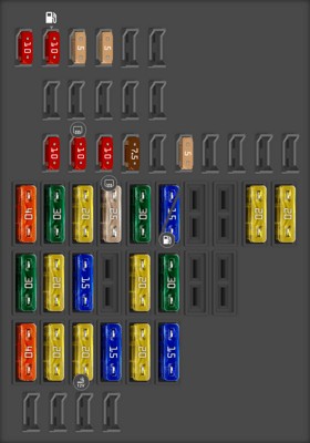
This table details the fuses within the interior panel, helping you pinpoint the fuse related to a specific malfunctioning component inside your Jetta.
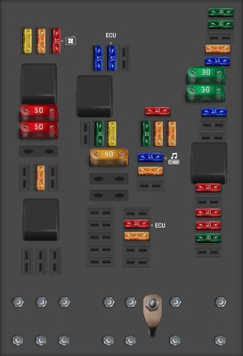
Engine Fuse Panel (Version B, High Box)
Located in the engine compartment, the Engine Fuse Panel (Version B, High Box) manages critical engine and powertrain functions. This is usually situated near the battery or engine control unit under the hood.
Here’s the fuse allocation for the Engine Fuse Panel (Version B, High Box):
| Fuse Type | Fuse No. | Description |
|---|---|---|
| ATO 30A | F1 | ABS control unit |
| ATO 30A | F2 | ABS control unit |
| ATO 5A | F4 | Onboard power supply control unit |
| ATO 15A | F5 | Onboard power supply control unit |
| ATO 15A | F6 | Fuel pressure regulating valve |
| ATO 10A | F9 | Charge pressure control solenoid valve, Activated charcoal filter system solenoid valve 1, Turbocharger air recirculation valve |
| ATO 10A | F11 | Lambda probe |
| ATO 10A | F12 | Lambda probe after catalytic converter |
| ATO 30A | F13 | Mechatronics for direct shift gearbox |
| ATO 10A | F15 | Circulation pump |
| ATO 5A | F16 | Steering column electronics control unit |
| ATO 5A | F17 | Control unit in dash panel insert |
| ATO 30A | F18 | Digital sound package control unit |
| ATO 15A | F19 | Radio and Navigation system control unit (R-Radio) |
| ATO 5A | F20 | Mobile telephone operating electronics control unit |
| ATO 10A | F23 | Motronic current supply relay, Engine control unit |
| ATO 5A | F24 | Data bus diagnostic interface |
| ATO 15A | F28 | Engine control unit |
| ATO 15A | F29 | Continued coolant circulation relay |
| ATO 20A | F30 | Auxiliary heater control unit |
| ATO 30A | F31 | Wiper motor control unit |
| ATO 10A | F38 | Inlet camshaft control valve 1, Radiator fan |
| ATO 5A | F39 | Clutch position sender |
| ATO 20A | F40 | Ignition coils with output stages |
| ATO 5A | F42 | Engine component current supply relay |
| MAXI 30A | F47 | Onboard power supply control unit |
| MAXI 30A | F48 | Onboard power supply control unit |
| MAXI 40A | F49 | Terminal 15 voltage supply relay |
| MAXI 50A | F52 | Contact relief relay |
| MAXI 50A | F53 | Driver seat adjustment thermal fuse 1, Fuse 32 on fuse holder C |
| MAXI – | F54 | Vacant |
This diagram and table will assist in diagnosing issues related to the engine and its supporting systems.
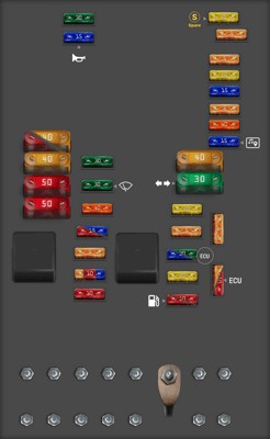
Engine Fuse Panel (Version A, Low Box)
The Engine Fuse Panel (Version A, Low Box) is another configuration found in some 2007 Jetta models. Like Version B, it is located in the engine bay and protects vital engine and vehicle operation circuits.
Here is the fuse assignment for the Engine Fuse Panel (Version A, Low Box):
| Fuse Type | Fuse No. | Description |
|---|---|---|
| ATO 20A | F1 | Spare |
| ATO 5A | F2 | Electronic Steering Column Control Unit |
| ATO 5A | F3 | Onboard Network Control Unit |
| ATO 20A | F4 | ABS Control Unit |
| ATO 15A | F5 | Mechatronic Control Unit for DSG Automatic Transmission |
| ATO 5A | F6 | Instrument Cluster Control Unit |
| ATO 40A | F7 | Voltage Supply Relay Terminal 15 |
| ATO 15A | F8 | Radio and Navigation Control Unit |
| ATO 5A | F9 | Telephone |
| ATO 5A | F10 | Power Supply Relay for Motronic/Voltage Supply Relay Terminal 30/Engine Control Unit (various engine codes) |
| ATO 20A | F11 | Additional Heating |
| ATO 5A | F12 | Diagnostic Interface for Data Bus |
| ATO 15A/30A | F13 | Engine Control Unit/Mechatronic Control Unit for DSG Automatic Transmission (various engine codes) |
| ATO 20A | F14 | Ignition Coils with Final Power Stage (specific engine codes) |
| ATO 10A | F15 | Fuel Pump Relay/Control Unit for Automatic Preheating Cycle/Lambda Sensors/NOx Sensor Control Unit (various engine codes) |
| ATO 30A | F16 | ABS Control Unit |
| ATO 15A | F17 | Horn, Onboard Network Control Unit |
| ATO 30A | F18 | Sound System |
| ATO 30A | F19 | Windshield Wipers |
| ATO 40A | F20 | Coolant Circulation Pump |
| ATO 10A | F21 | Lambda Sensor/Lambda Sensor 2/Post-Catalyst Lambda Sensor/Electromagnetic Clutch for Compressor (various engine codes) |
| ATO 5A | F22 | Clutch Position Transmitter |
| ATO 5A/10A/15A | F23 | Secondary Air Relay/Exhaust Gas Recirculation Valve/Solenoid Valve for Boost Pressure Limitation/Radiator Switching Valve for Exhaust Gas Recirculation/Fuel Pressure Regulator Valve (various engine codes) |
| ATO 10A | F24 | Thermostat for Engine Cooling/Relay for Auxiliary Coolant Pump/Solenoid Valve 1 for Activated Charcoal Canister/Variable Intake Manifold Switching Valve/Valve -1- for Variable Distribution/Intake Manifold Flap Valve/Coolant Fan/Intake Manifold Flap Motor (various engine codes) |
| MAXI 40A | F25 | ABS Control Unit, ABS Hydraulic Pump |
| MAXI 30A | F26 | Turn Signals, Brake Light, Fog Lights, Parking Lights, Headlight |
| MAXI 50A | F27 | Control Unit for Automatic Preheating Cycle/Secondary Air Pump Motor (specific engine codes) |
| MAXI 40A | F28 | Voltage Supply Relay Terminal 15, Discharge Relay for Contact X (l/1) |
| MAXI 50A | F29 | Thermal Fuse 1 for Driver’s Seat Adjustment, Fuse 34 in Fuse Holder C |
| MAXI 50A | F30 | Discharge Relay for Contact X (l/1) |
Refer to this diagram to understand the fuse layout if your 2007 Jetta has the Version A low box engine fuse panel.
By using these 2007 Jetta Fuse Box Diagrams and descriptions, you can confidently diagnose and repair electrical issues in your vehicle. Always ensure you are using the correct diagram for your specific model year and fuse box type for accurate troubleshooting.