Hey fellow car DIY enthusiasts! I’ve hit a snag while developing a project for my car and could really use some expert eyes on my setup. I’m working on integrating an Arduino Pro Mini into my car’s 12V system, specifically focusing on using a 12v Switch For Car functionality.
Over the weekend, I moved from breadboard testing to a prototype perfboard to test the code directly in my car. Unfortunately, I’ve run into a frustrating problem: I’ve managed to blow two Arduino Pro Minis already! Initially, I suspected a current limiting resistor issue with the BJTs, and after addressing that, the second Arduino failed in the same way. It seems pins 9, 8, and 7 are getting shorted, and both times, a BJT also blew.
The problem arose when I was testing two main parts of the circuit. First, the ignition sensing part, which uses a voltage divider, seemed to work correctly. Then, I moved on to testing the door switch circuit, incorporating a diode as shown in the schematic.
On the cathode side of the diode, the readings were as expected: 0V when the door was opened (simulating the 12v switch for car being off) and 12V when the door was closed (12v switch for car being on).
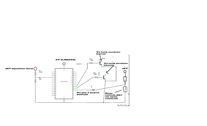 Schematic diagram of the car circuit
However, the Arduino never registered the switch from high to low. That’s when I noticed some pins had blown, and the ATmega chip started overheating on both Pro Minis. While the Arduinos aren’t completely unusable (analog pins are still functional), on the second attempt, the TX/RX pins seem to be fried as well, as I’ve lost serial communication, although my HC-05 Bluetooth module still works.
I’m including my schematic here. Can anyone spot the error in my design that might be causing these Arduino failures when interacting with the 12v switch for car circuit?
I realize now that Pin 7, which is configured with input pull-up, lacks a diode to +5V as typically recommended. However, these tests were conducted with the engine off, so I didn’t expect any negative voltage spikes to occur during this stage. Any insights or suggestions would be greatly appreciated!