Welcome back to Gearhead 101 — a series dedicated to explaining the fundamentals of car mechanics for everyone, from beginners to seasoned auto aficionados. In our previous articles, we’ve explored the intricacies of car engines and how engine power is transferred through the drivetrain. We also demystified the workings of the manual transmission, that essential power switchboard between the engine and wheels.
Today, we shift our focus to a component found in the majority of vehicles on the road, particularly in the United States: the automatic transmission. Have you ever pondered the magic behind your car seamlessly selecting the right gear, requiring nothing more from you than pressing the accelerator or brake pedal?
Prepare to be amazed. We are about to embark on a journey into one of the most impressive feats of mechanical and fluid engineering ever conceived: the automatic transmission. Understanding the Automatic Gearbox Diagram and the system it represents is truly awe-inspiring, especially when you consider it was developed without the aid of modern computers.
Revisiting the Core Function of a Transmission
Before we delve into the detailed workings of an automatic transmission and its corresponding automatic gearbox diagram, let’s quickly recap the fundamental purpose of any transmission in a vehicle.
As we covered in our guide on car engines, the engine generates rotational power. This power needs to be effectively transferred to the wheels to propel the car forward. This is where the drivetrain comes in, and the transmission is a critical part of this system.
The challenge lies in the engine’s operational limitations. Engines are designed to spin efficiently within a specific speed range. Too slow, and the car won’t move from a standstill; too fast, and engine damage is a real risk.
Therefore, a transmission is essential to modulate the engine’s power output. It multiplies the engine’s power when needed—like starting from a stop or climbing a hill—and reduces it when less power is required, such as when driving downhill or at high speeds, or when braking.
In essence, the transmission ensures the engine operates at its optimal speed while delivering the precise amount of power to the wheels for any driving situation. Positioned between the engine and the rest of the drivetrain, it acts as a sophisticated power management system for your car.
We previously discussed how manual transmissions achieve this using gear ratios. By engaging different sized gears, manual transmissions alter the power delivered without drastically changing engine speed. If gear ratios are still unclear, reviewing the video from our previous article is highly recommended before proceeding, as this concept is fundamental to understanding transmissions.
Manual transmissions put gear selection under the driver’s control via a clutch and gear shift. Automatic transmissions, however, automate this process through ingenious engineering, engaging the appropriate gear based on driving conditions, all without driver intervention beyond using the pedals. It’s truly a marvel of automotive engineering.
Exploring the Components of an Automatic Transmission
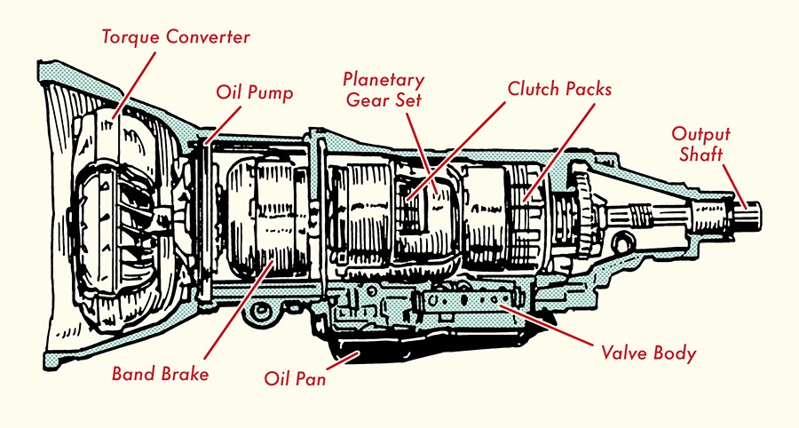
By this point, you should grasp the core function of a transmission: maintaining optimal engine speed while delivering the necessary power to the wheels across various driving conditions. Now, let’s dissect the components that enable automatic transmissions to perform this function, referencing the automatic gearbox diagram to visualize each part.
Transmission Casing
The transmission casing is the protective shell that encloses all internal components of the automatic transmission. Often called a “bell casing” due to its bell-like shape, it is typically constructed from aluminum. Beyond safeguarding the transmission’s gears and mechanisms, modern transmission casings also house various sensors. These sensors monitor the rotational speed entering the transmission from the engine and the rotational speed exiting towards the rest of the vehicle.
Torque Converter
Have you ever wondered how your car can start and idle without immediately moving? This is because the power flow from the engine to the transmission is initially disconnected. This disconnection allows the engine to run even when the drivetrain is stationary. In a manual transmission, this disconnection is achieved by depressing the clutch pedal.
But how is power disengaged in an automatic transmission, which lacks a clutch pedal? The answer lies in the torque converter.
This is where the ingenious mechanics of automatic transmissions truly begin to shine. The torque converter is a pivotal component, acting as the hydraulic link between the engine and the transmission, even before we consider the complexity of planetary gears.
Positioned between the engine and the transmission, the torque converter resembles a donut shape and resides within the bell casing. It performs two essential functions in transmitting torque:
- It transfers power from the engine to the transmission input shaft.
- It multiplies the engine torque output.
These functions are achieved through hydraulic power, utilizing the transmission fluid within the system. To fully understand this, we need to examine the internal parts of a torque converter.
Internal Components of a Torque Converter
Most modern torque converters consist of four primary parts: 1) the pump, 2) the stator, 3) the turbine, and 4) the torque converter clutch.
1. Pump (Impeller): The pump, or impeller, looks similar to a fan with radiating blades. It is directly mounted to the torque converter housing, which is then bolted to the engine’s flywheel. Consequently, the pump rotates at the same speed as the engine’s crankshaft. This synchronized rotation is crucial for the torque converter’s operation. The pump’s function is to “pump” transmission fluid outward from its center towards the turbine.
2. Turbine: The turbine is located within the converter housing, also resembling a fan in appearance. It is directly connected to the transmission’s input shaft but is not physically connected to the pump, allowing it to rotate at a different speed. This independence is vital, as it enables the engine and drivetrain to operate at varying speeds as needed.
The turbine spins due to the transmission fluid propelled by the pump. The turbine blades are designed to direct the fluid towards the center of the turbine and back towards the pump, creating a continuous fluid circuit.
3. Stator (Reactor): Positioned between the pump and turbine, the stator resembles a fan blade or an airplane propeller. It serves two crucial purposes: 1) to efficiently redirect transmission fluid from the turbine back to the pump, and 2) to multiply the torque from the engine, especially during initial acceleration, while reducing torque at cruising speeds.
The stator achieves this through clever design and mechanics. First, its blades are shaped to redirect the fluid exiting the turbine in the same direction as the pump’s rotation.
Second, the stator is connected to a fixed shaft on the transmission via a one-way clutch. This clutch allows the stator to rotate in only one direction, ensuring consistent fluid flow direction. The stator remains stationary until the fluid speed from the turbine reaches a certain threshold.
These design features enhance the pump’s efficiency and increase fluid pressure. This, in turn, amplifies the torque at the turbine. Because the turbine is connected to the transmission, this increased torque is effectively transferred to the transmission and the rest of the drivetrain.
4. Torque Converter Clutch: Due to the nature of fluid dynamics, some power is inevitably lost as transmission fluid travels from the pump to the turbine. This results in the turbine rotating slightly slower than the pump. While this speed difference is beneficial for torque multiplication during acceleration, it introduces energy inefficiency at cruising speeds.
To counter this, modern torque converters often include a torque converter clutch connected to the turbine. When the vehicle reaches a certain speed (typically around 45-50 mph), the torque converter clutch engages, mechanically locking the turbine to the pump, forcing them to rotate at the same speed. A computer system controls the engagement of this clutch to optimize efficiency.
These components work in concert to make the torque converter function effectively.
Let’s visualize the torque converter in action as you accelerate from a standstill to cruising speed:
When you start the car and it idles, the pump spins at engine speed, pushing transmission fluid towards the turbine. However, at idle speed, the fluid movement is insufficient to rotate the turbine significantly, so minimal torque is delivered to the transmission.
As you press the accelerator, the engine speed increases, causing the torque converter pump to spin faster. This increased pump speed accelerates the transmission fluid, generating enough force to spin the turbine more rapidly. The turbine then directs the fluid towards the stator. Initially, the stator remains stationary because the fluid speed isn’t high enough to cause it to rotate.
However, the stator’s blade design redirects the fluid back to the pump in the same direction as the pump’s rotation. This redirection aids the pump in moving fluid back towards the turbine at a higher speed and pressure. As the fluid returns to the turbine with greater force, it delivers amplified torque to the turbine, which in turn transmits more torque to the transmission, initiating vehicle movement.
This cycle repeats and intensifies as the car accelerates. Upon reaching cruising speed, the transmission fluid pressure reaches a point where it causes the stator blades to begin rotating. With the stator rotating, torque multiplication decreases, as less torque is needed to maintain speed. At this point, the torque converter clutch engages, locking the turbine and pump to rotate at the same speed as the engine, eliminating slippage and maximizing efficiency.
In summary, the torque converter facilitates and regulates power transmission from the engine to the transmission, and crucially, it multiplies torque to enable smooth starts from a standstill. Now, let’s explore the components that enable automatic gear shifting: planetary gears.
Planetary Gears
As a vehicle gains speed, the torque required to maintain that speed diminishes. Transmissions adjust the torque delivered to the wheels through gear ratios. Lower gear ratios provide higher torque, while higher gear ratios deliver less torque but higher speed.
In manual transmissions, the driver manually selects gear ratios. Automatic transmissions, however, change gear ratios automatically using planetary gears. The planetary gear system’s ingenious design is what allows for these automatic shifts.
A planetary gear set comprises three main components:
- Sun Gear: Located at the center of the planetary gear set.
- Planet Gears/Pinions and Carrier: Typically three or four smaller gears that encircle the sun gear and are constantly meshed with it. These planet gears are mounted on a carrier, allowing them to rotate on their axes and orbit the sun gear.
- Ring Gear: An outer gear with internal teeth that surrounds the entire gear set. Its teeth are constantly meshed with the planet gears.
A single planetary gear set can achieve reverse and multiple forward gear ratios. The ratio achieved depends on which component—sun gear, planet carrier, or ring gear—acts as the input, output, or is held stationary.
Let’s examine how different gear ratios are achieved by varying the roles of these components.
Sun Gear Input / Planetary Carrier Output / Ring Gear Stationary
In this configuration, the sun gear serves as the input, and the ring gear is held stationary. As the sun gear rotates, the planet gears, meshed with both the sun gear and the fixed ring gear, are forced to rotate and “walk” around the inside of the ring gear in the opposite direction of the sun gear. This movement causes the planet carrier, which supports the planet gears, to rotate in the same direction as the sun gear but at a reduced speed. The carrier thus becomes the output.
This arrangement creates a gear reduction, meaning the input gear (sun gear) rotates faster than the output gear (planet carrier). However, the torque output at the planet carrier is significantly higher than the torque input at the sun gear. This configuration is typically used for starting the vehicle or in low gear for maximum torque.
Ring Gear Input / Planetary Carrier Output / Sun Gear Stationary
Here, the ring gear is the input, and the sun gear is held stationary. When the ring gear rotates, the meshed planet gears are compelled to rotate and orbit around the fixed sun gear. This orbital motion drives the planet carrier, which then becomes the output, rotating in the same direction as the ring gear.
This configuration provides a slightly higher gear ratio than the previous one. The input (ring gear) still rotates faster than the output (planet carrier), resulting in torque multiplication, though less than in the previous setup. This configuration is commonly used for intermediate gears during acceleration or when climbing inclines.
Sun Gear and Ring Gear Input / Planetary Carrier Output (Direct Drive)
In this scenario, both the sun gear and the ring gear act as inputs, rotating at the same speed and direction. This synchronized input causes the planet gears to cease rotating on their individual axes. Because the ring gear and sun gear are driving the planet gears in opposing directions simultaneously, the planet gears effectively lock up. Consequently, the entire planetary gear set—sun gear, planet carrier, and ring gear—rotates as a single unit at the same speed. In this arrangement, the input and output speeds are identical, resulting in a 1:1 gear ratio, known as direct drive.
Direct drive is typically engaged at cruising speeds around 45-50 mph for efficient power transfer without torque multiplication or reduction.
Planetary Carrier Input / Ring Gear Output / Sun Gear Stationary (Overdrive)
In this overdrive configuration, the planet carrier becomes the input, and the sun gear is held stationary. As the planet carrier rotates, it forces the planet gears to orbit around the fixed sun gear. This orbital motion drives the ring gear to rotate faster than the planet carrier, in the same direction. One rotation of the planet carrier results in more than one rotation of the ring gear, creating a gear ratio greater than 1:1, known as overdrive. Overdrive provides increased output speed but reduced torque.
Overdrive gears are engaged at high speeds, such as highway driving above 60 mph, to improve fuel efficiency and reduce engine wear by allowing the engine to run at lower RPMs for a given vehicle speed.
Automatic transmissions typically incorporate multiple planetary gear sets working in conjunction to achieve a wider range of gear ratios. Because the gears in a planetary system are constantly meshed, gear changes are seamless and occur without the interruption of power flow characteristic of manual transmissions.
But how does the automatic transmission control which components of the planetary gear system are input, output, or stationary to achieve these varying gear ratios? This is managed by brake bands and clutches within the transmission.
Brake Bands and Clutches
Brake bands are curved strips of metal lined with friction material. They are designed to clamp down on the outer surface of rotating components, such as the ring gear or sun gear, to hold them stationary or release to allow them to rotate freely. The application and release of brake bands are controlled by a hydraulic system within the transmission.
In addition to brake bands, automatic transmissions utilize a series of clutches to engage and disengage different parts of the planetary gear system. These clutches, often multi-disc clutches, consist of interleaved metal and friction plates. When hydraulic pressure is applied, these plates are pressed together, engaging the clutch and connecting the selected planetary gear component to either the power input or to a stationary part of the transmission housing. By selectively engaging and disengaging clutches and brake bands, the transmission control system can manipulate which parts of the planetary gear sets are active, thereby changing gear ratios automatically. The precise orchestration of clutches and brake bands is determined by a combination of mechanical, hydraulic, and electronic controls, all working in harmony to provide smooth and automatic gear shifts.
The intricate dance of clutches and brake bands controlling the planetary gears is complex and best understood visually. For a detailed visual explanation, the following video is highly recommended:
[Insert Recommended Video Link Here – Original article links to a YouTube video, which should be linked here]
How an Automatic Transmission Operates: A System Overview
As you can see from the automatic gearbox diagram and our component breakdown, automatic transmissions are complex systems. They seamlessly integrate mechanical, fluid, and electrical engineering to provide a smooth driving experience from a complete stop to highway speeds.
Let’s summarize the power flow through an automatic transmission:
- The engine delivers power to the torque converter pump.
- The pump transmits power to the torque converter turbine via transmission fluid.
- The turbine redirects the transmission fluid back to the pump through the stator.
- The stator multiplies the fluid’s power, enhancing the power transferred back to the turbine, creating a circulating power loop within the torque converter.
- The turbine, connected to the transmission input shaft, transfers rotational power to the planetary gear sets within the transmission.
- Based on signals from sensors and the transmission control system, specific multi-disc clutches and brake bands are engaged or disengaged.
- This engagement determines whether the sun gear, planet carrier, or ring gear of each planetary gear set acts as the input, output, or stationary component.
- The configuration of each planetary gear set dictates the gear ratio, ultimately determining the torque and speed delivered to the drivetrain and wheels.
This overview provides a broad understanding of automatic transmission operation. Sensors and control valves continuously monitor and adjust the system, but this captures the fundamental process.
Visualizing this process is highly beneficial. We again recommend watching the video linked earlier, as the background provided here will enhance your understanding of the visual explanations.
As we said at the outset, the automatic transmission is an extraordinary piece of engineering.
Now, as you experience your car smoothly shifting gears while driving, you’ll have a much clearer understanding of the sophisticated mechanics at work beneath the surface.
Related Posts
[Links to related articles from original article – if applicable]
Tags: Cars Previous Next