The Controller Area Network (CAN bus) is the backbone of modern automotive communication. If you’re involved in car repair, diagnostics, or automotive technology, understanding the CAN bus is essential. This guide provides a comprehensive yet accessible introduction to CAN bus systems in cars, detailing everything from its fundamental principles to its practical applications in diagnostics and data analysis.
What is CAN Bus in Cars?
Imagine the human body’s nervous system – that’s essentially what the CAN bus is for your car. The CAN bus (Controller Area Network) is a specialized communication network that allows Electronic Control Units (ECUs) within your vehicle to talk to each other efficiently and reliably without needing a central computer. Think of ECUs as the different organs in your car: engine control, braking systems, transmission, and more. The CAN bus is the network of nerves that allows them to coordinate and function as a cohesive unit.
In a car, the CAN bus physically consists of a two-wire system, a twisted pair of wires known as CAN high and CAN low. These wires, often color-coded yellow (CAN high) and green (CAN low), act as the communication highway for all the ECUs in your vehicle.
Image alt text: Diagram illustrating a car’s CAN bus system, highlighting the interconnected network of ECUs for communication and control.
Image alt text: Close-up of a twisted pair CAN bus wiring harness, showing the yellow (CAN high) and green (CAN low) wires commonly used in automotive applications.
Image alt text: Conceptual overview of CAN bus communication within a car, depicting ECUs sending and receiving messages on the network, with some messages being accepted and others rejected based on relevance.
Understanding ECUs in Automotive CAN Networks
Electronic Control Units (ECUs) are the dedicated control systems within your car, each managing specific functions. From the engine control unit managing performance to the transmission ECU controlling gear shifts, and brake ECUs ensuring safe stopping, a modern car can easily contain over 70 ECUs. Each of these units needs to share data across the vehicle’s systems. The CAN bus makes this possible.
Any ECU connected to the CAN bus can broadcast information. For example, a sensor ECU might detect wheel slip and broadcast this data. Every other ECU on the network receives this broadcast, but each ECU then decides whether to act on this information or ignore it based on its programming. This broadcast mechanism is fundamental to how CAN bus facilitates communication in cars.
Diving deeper into an ECU, we find three key components:
- Microcontroller (MCU): This is the ECU’s brain, processing incoming CAN messages and deciding which messages to send. For instance, an oil temperature sensor’s MCU might be programmed to transmit temperature readings every few seconds.
- CAN Controller: Usually integrated into the MCU, the CAN controller handles the complexities of the CAN protocol, such as message encoding, error detection, and arbitration. This simplifies the MCU’s job, allowing it to focus on the ECU’s core functions.
- CAN Transceiver: This is the interface between the CAN controller and the physical CAN wires. It converts data from the controller into signals that can travel over the CAN bus and vice versa. It also provides critical electrical protection for the ECU.
Image alt text: Diagram of an ECU (Electronic Control Unit) as a CAN bus node, showing its internal components: Microcontroller, CAN Controller, and CAN Transceiver, highlighting its role in the car’s network.
Image alt text: Pinout diagram of a CAN bus DB9 connector, detailing pin assignments for CAN high, CAN low, ground, and power, a common connector type used in automotive CAN bus interfaces.
Connecting to the CAN Bus in Your Car: The DB9 Connector
While there isn’t a single, universal connector for CAN bus systems across all car manufacturers, the DB9 (D-sub9) connector is a strong contender and often used, particularly in diagnostic tools and CAN bus data loggers. Though specific vehicle models might employ different connectors, the DB9 serves as a widely recognized standard for accessing CAN bus networks in many automotive applications.
CAN Bus Variants Relevant to Cars
It’s important to know that the CAN bus technology has evolved, leading to several variants, each with different capabilities and applications in cars:
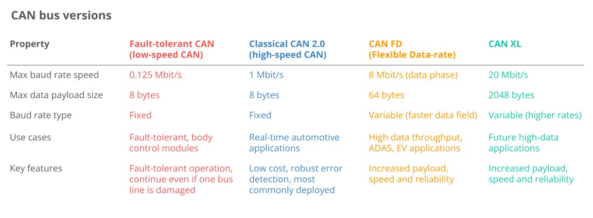
- High-Speed CAN (Classical CAN): This is the most prevalent type in today’s cars and the primary focus of this article. It offers a good balance of speed and reliability for most in-vehicle communication needs.
- CAN FD (Flexible Data-Rate): CAN FD is a newer, faster version of CAN, designed to handle larger data payloads and higher speeds. While adoption in cars is growing, it’s not yet as widespread as Classical CAN. Learn more in our CAN FD intro.
- Low-Speed CAN (Fault-Tolerant CAN): This variant is designed for robustness and fault tolerance at lower speeds. However, it’s increasingly being replaced by LIN bus for cost-sensitive applications in cars.
- CAN XL: The latest evolution, CAN XL, offers even greater data capacity and speed, bridging the gap between CAN and Automotive Ethernet. While not yet common in cars on the road today, it represents the future of high-bandwidth automotive networking.
In addition to CAN, cars often incorporate other networking technologies:
- LIN Bus: Local Interconnect Network (LIN) is a lower-cost, slower communication system often used for less critical functions in cars, like window controls or air conditioning. It typically operates as a sub-network connected to the CAN bus via a master node. For more detail, see our LIN bus intro or LIN bus data logger article.
- FlexRay: FlexRay offers higher speed and fault tolerance than CAN and was used in some automotive applications requiring high reliability and bandwidth. However, it’s more complex and expensive than CAN, and its role is diminishing with the rise of Automotive Ethernet and CAN FD.
- Automotive Ethernet: Automotive Ethernet is increasingly being adopted in cars to support high-bandwidth applications like advanced driver-assistance systems (ADAS), infotainment, and cameras. While it offers much faster data rates than CAN, it’s often used in conjunction with CAN bus, which remains crucial for safety-critical systems and core vehicle control.
Top 4 Benefits of CAN Bus in Cars
The widespread adoption of CAN bus in virtually all cars and vehicles is due to its significant advantages:
Image alt text: Icon depicting the benefit of CAN bus as low cost and simple, illustrating reduced wiring complexity and cost-effectiveness in car manufacturing.
1. Simplicity and Low Cost
CAN bus significantly reduces complexity and cost in car wiring systems. Instead of point-to-point wiring, where each component needs a direct wire to every other component it communicates with, CAN bus uses a shared network. This leads to:
- Reduced Wiring Harness Complexity: Imagine the wiring nightmare if every sensor and control unit needed its own set of wires! CAN bus simplifies this dramatically, using a single bus line for numerous devices. This is similar to the advantage of NMEA 2000 over NMEA 0183 in marine electronics.
- Weight Reduction: Less wiring translates directly to less weight. Switching to CAN bus can reduce a car’s wiring harness weight by up to 20 kg, improving fuel efficiency and overall vehicle performance.
- Economies of Scale: The sheer volume of CAN bus usage in the automotive industry drives down the cost of components like controllers, transceivers, and wiring. This makes CAN bus a very economical solution for car manufacturers.
Image alt text: Icon illustrating CAN bus as a centralized system for easy access, depicting centralized data logging and diagnostics capabilities in cars.
2. Easy Access for Diagnostics and Data Logging
CAN bus provides a central access point to all the ECUs in a car network. This is invaluable for:
- Centralized Diagnostics: With CAN bus, diagnostic tools can connect at any point on the network to access data from all ECUs. This greatly simplifies car diagnostics, eliminating the need to individually probe each component.
- Silent CAN Logging: CAN bus data logging can be performed passively, without interfering with the normal operation of the car’s network. This ‘silent mode’ is crucial for capturing accurate data during diagnostics and troubleshooting.
- ECU Flashing and Updates: Software updates and firmware flashing for ECUs can be performed over the CAN bus. Higher-layer protocols like UDS or CCP/XCP are typically used for this purpose.
- Standardization: The automotive industry has embraced standardized higher-layer protocols on CAN bus, improving interoperability of diagnostic tools and systems across different car brands and models.
Image alt text: Icon representing CAN bus robustness, showing a shield protecting against electromagnetic interference, highlighting its reliability in harsh automotive environments.
3. Extreme Robustness and Reliability
Cars operate in electrically noisy environments. CAN bus is designed to be highly robust against electrical disturbances and electromagnetic interference (EMI), making it ideal for safety-critical automotive applications:
- Differential Signaling: CAN bus uses differential signaling, meaning data is transmitted as the voltage difference between the CAN high and CAN low wires. EMI affects both wires equally, so the voltage difference, and thus the data signal, remains largely unaffected.
- Comprehensive Error Handling: CAN bus incorporates extensive error detection mechanisms, including bit errors, stuff errors, CRC errors, form errors, and ACK errors. If errors are detected, the system is designed to automatically retransmit faulty messages, ensuring data integrity. Learn more about CAN errors.
- Error Confinement: CAN nodes are designed to monitor their own error counts. If a node becomes excessively error-prone, it can temporarily or permanently disconnect itself from the bus (‘bus off’) to prevent it from disrupting the entire network.
Image alt text: Icon depicting CAN bus efficiency through a priority system, illustrating prioritized message transmission and efficient bus utilization in automotive communication.
4. Efficiency and Prioritization
CAN bus is designed for efficient communication, especially in time-critical automotive applications:
- Message Prioritization via Arbitration: When multiple ECUs attempt to transmit data simultaneously, CAN bus uses a priority system based on message IDs. Messages with lower IDs (higher priority) are transmitted first, while lower priority messages automatically back off and retry later. This arbitration mechanism prevents data collisions and ensures critical messages get through without delay.
- Efficient Bandwidth Utilization: The arbitration process also helps maximize CAN bus bandwidth utilization. Lower priority messages can effectively fill in the gaps between high-priority transmissions.
- Sufficient Speed: While Classical CAN might be considered slower than technologies like Automotive Ethernet, it provides ample speed for the vast majority of automotive control and communication needs. A 1 Mbit/s CAN bus can handle thousands of messages per second.
A Brief History of CAN Bus in Automotive
- Pre-CAN Era: Early car electronics relied on complex and inefficient point-to-point wiring systems.
- 1986: Bosch developed the CAN protocol as a solution to simplify in-vehicle networking.
- 1991: Bosch released CAN 2.0, defining the standard message formats (CAN 2.0A with 11-bit IDs and 2.0B with 29-bit IDs).
- 1993: CAN was adopted as an international standard (ISO 11898), solidifying its place in automotive and industrial applications.
- 2003: ISO 11898 became a series of standards, further defining different aspects of CAN.
- 2012: Bosch introduced CAN FD (Flexible Data-Rate) 1.0, offering increased bandwidth for growing data demands.
- 2015: CAN FD protocol was standardized (ISO 11898-1).
- 2016: Physical layer standards for CAN FD (ISO 11898-2) were updated to support data rates up to 5 Mbit/s (and practically up to 8 Mbit/s).
- 2018: CiA began development of CAN XL, pushing CAN capabilities even further.
- 2024: CAN XL was standardized (ISO 11898-1:2024, 11898-2:2024), paving the way for future automotive applications requiring very high bandwidth.
Today, CAN is a ubiquitous standard in cars, trucks, buses, agricultural vehicles, and many other types of vehicles and machines.
Image alt text: Illustration showcasing diverse applications of CAN bus logging, including buses, trucks, machines, tractors, and automotive vehicles, highlighting its broad use across vehicle types.
Image alt text: Timeline of CAN bus history from 1986 to 2018, marking key milestones in its development and standardization for automotive and industrial networking.
Image alt text: Graphic depicting the future of CAN bus in connected vehicles, cloud computing, and IoT, indicating its evolution towards advanced automotive and telematics systems.
The Future of CAN Bus in Cars
The CAN bus protocol will remain a critical technology in the automotive sector, even as the industry evolves:
- Demand for Higher Speed: The increasing complexity of car systems, especially ADAS and autonomous driving features, is driving demand for higher data rates. This will likely lead to greater adoption of CAN FD, CAN XL, and Automotive Ethernet in cars.
- Connected Cars and Vehicle Telematics: The rise of cloud connectivity and vehicle telematics opens new possibilities for predictive maintenance, remote diagnostics, and over-the-air updates. However, it also raises cybersecurity concerns.
- Open vs. Closed Automotive Data: The push for ‘Open Source’ and Right to Repair in the automotive industry may clash with OEMs’ desire to keep vehicle data proprietary for new subscription-based services and control.
Despite the emergence of newer technologies, the transition away from Classical CAN in cars will be gradual. While CAN FD is gaining traction, and Automotive Ethernet is crucial for high-bandwidth applications, Classical CAN remains deeply embedded in existing car architectures and will likely coexist with these newer technologies for many years to come.
Get Our ‘Ultimate CAN Guide’
Want to become a CAN bus expert for car diagnostics and repair?
Download our comprehensive 160+ page PDF guide, featuring 12 ‘simple intros’ to CAN bus and related technologies:
Download now
Image alt text: Cover image of the “CAN Bus – The Ultimate Guide Tutorial PDF,” advertising a comprehensive resource for learning about CAN bus technology in automotive and other applications.
CAN Bus Physical and Data Link Layers in Cars
From a technical perspective, CAN bus is defined by two layers in the OSI model: the physical layer and the data link layer. For High-Speed CAN used in cars, ISO 11898-1 standardizes the data link layer, and ISO 11898-2 standardizes the physical layer.
Image alt text: Diagram illustrating the CAN bus OSI model, highlighting the physical layer (ISO 11898-2) and data link layer (ISO 11898-1) as the foundation for CAN communication in automotive networks.
Physical Layer (ISO 11898-2)
The physical layer defines the hardware aspects of the CAN bus in cars, including:
- Baud Rate: Specifies the data transmission speed. Classical CAN in cars typically operates up to 1 Mbit/s, while CAN FD can reach up to 8 Mbit/s.
- Cable Length: Maximum cable lengths are defined to ensure signal integrity, ranging from 500 meters at 125 kbit/s to 40 meters at 1 Mbit/s. In cars, cable lengths are generally much shorter.
- Termination: The CAN bus in cars, like in other applications, requires 120 Ohm termination resistors at each end of the bus to prevent signal reflections.
- Cable Type and Impedance: Specifies the type of cable (typically twisted pair) and impedance characteristics required for reliable communication.
Data Link Layer (ISO 11898-1)
The data link layer governs the communication protocols and data handling on the CAN bus in cars:
- Frame Formats: Defines the structure of CAN messages, including data frames, remote frames, error frames, and overload frames, with both 11-bit and 29-bit identifiers.
- Error Handling: Specifies the robust error detection and handling mechanisms, including CRC, acknowledgement slots, and error counters, ensuring reliable data exchange in cars.
- Arbitration: The non-destructive bitwise arbitration method ensures fair and prioritized access to the CAN bus, crucial for real-time communication in cars.
Understanding the CAN Frame in Cars
Communication on the CAN bus in cars happens through CAN frames. The most common type in cars is the standard CAN data frame with an 11-bit identifier (CAN 2.0A). The extended 29-bit identifier frame (CAN 2.0B), while also used, is less frequent in standard automotive applications but is common in protocols like J1939 used in heavy-duty vehicles.
When analyzing CAN bus data from cars, the CAN ID and Data fields are particularly important.
Image alt text: Detailed breakdown of a standard CAN bus frame structure, labeling each field: SOF, ID, RTR, Control, Data, CRC, ACK, and EOF, essential for understanding CAN message anatomy in automotive diagnostics.
Key components of a CAN frame include:
- SOF (Start of Frame): A dominant ‘0’ bit that signals the beginning of a CAN frame transmission.
- ID (Identifier): An 11-bit (or 29-bit in extended frames) identifier that serves two purposes: message priority (lower value = higher priority) and message filtering. In cars, IDs are crucial for identifying message types (e.g., engine speed, temperature).
- RTR (Remote Transmission Request): Used to request data from another node. Less common in data frames, primarily used in remote frames.
- Control Field: Contains the IDE (Identifier Extension Bit) to differentiate between standard and extended frames and the DLC (Data Length Code) specifying the number of data bytes (0-8).
- Data Field: The payload of the CAN frame, containing 0 to 8 bytes of data. This is where sensor readings, control commands, and other information are carried. In car diagnostics, decoding this data is key.
- CRC (Cyclic Redundancy Check): A 15-bit checksum used for error detection, ensuring data integrity in automotive communication.
- ACK (Acknowledgement Slot): Used by receiving nodes to acknowledge successful reception of the CAN frame.
- EOF (End of Frame): Marks the end of the CAN frame transmission.
Four types of CAN frames exist:
- Data Frame: Carries data from a transmitter to one or more receivers. This is the most common frame type in car CAN bus communication.
- Error Frame: Transmitted by a node detecting an error, signaling to other nodes that a communication fault has occurred. Useful for diagnosing CAN bus issues in cars. See our intro to CAN errors.
- Remote Frame: Requests data from another node. Less frequently used in cars compared to data frames.
- Overload Frame: Used to insert delays between data or error frames, primarily for node synchronization. Rarely used in modern CAN bus systems in cars.
Valid CAN frame transmission is critical. If errors occur, CAN’s error handling mechanisms come into play. Nodes track error counters and can enter error states (active, passive, bus off) to manage bus errors and prevent network disruption. Understanding CAN bus error handling is important for advanced car diagnostics.
Higher-Layer CAN Protocols in Automotive
CAN bus, as a lower-layer protocol, provides the foundation for communication in cars but needs higher-layer protocols to define data interpretation and message handling beyond the basic frame structure. These protocols add layers of meaning and standardization to the raw CAN data.
Image alt text: OSI model diagram illustrating higher-layer protocols built upon the CAN bus data link and physical layers, showing the protocol stack for automotive communication.
Here are some of the most common higher-layer protocols used in automotive CAN bus systems:
OBD2 (On-Board Diagnostics II)
OBD2 is a standardized protocol mandated in most cars for emissions diagnostics and provides access to a range of diagnostic data, including diagnostic trouble codes (DTCs) and real-time parameters like engine speed (RPM) and vehicle speed.
UDS (Unified Diagnostic Services)
UDS is a more advanced diagnostic protocol used in automotive ECUs for comprehensive diagnostics, ECU reprogramming (flashing), and routine testing. It provides a standardized way to interact with ECUs for service and maintenance.
CCP/XCP (CAN Calibration Protocol / Universal Measurement and Calibration Protocol)
CCP and XCP are protocols used for ECU calibration, measurement, and flashing during vehicle development and testing. They allow engineers to read and write ECU memory for parameter tuning and software updates.
CANopen
While CANopen is more common in industrial automation, it can also be found in some automotive subsystems. It’s a protocol for embedded control applications, defining device profiles and communication mechanisms for interoperability.
SAE J1939
J1939 is primarily used in heavy-duty vehicles (trucks, buses) but can also be found in some specialized automotive applications. It defines parameters using Suspect Parameter Numbers (SPNs) organized in Parameter Group Numbers (PGNs) for vehicle network data.
NMEA 2000
NMEA 2000 is used in marine applications but shares similarities with J1939 and can be relevant in specialized vehicle applications that interface with marine systems.
ISOBUS (ISO 11783)
ISOBUS is used in agricultural and forestry machinery for communication between tractors and implements. While not directly in cars, it’s related to J1939 and represents another application of CAN bus in vehicle networks.
Understanding the distinction between CAN bus and higher-layer protocols is crucial for anyone working with car electronics. Think of it like this: CAN bus is the basic communication infrastructure, while higher-layer protocols are the languages spoken over that infrastructure.
Analogy: Imagine people communicating. CAN bus is like the ability to speak and understand basic grammar. Higher-layer protocols are like different languages (English, Spanish, etc.).
- Higher-layer protocol is always needed: Just as conversations need language, CAN bus communication in cars always uses a higher-layer protocol to give meaning to the raw data.
- Many protocols exist: Like languages, there are numerous higher-layer protocols. Automotive CAN bus systems use a variety of these, including standardized ones and car manufacturer-specific protocols.
- Data recording vs. interpretation: A voice recorder captures sounds, like a CAN logger captures raw CAN data. But to understand the conversation (or the CAN data), you need to know the language (or the higher-layer protocol).
- Multiple protocols in cars: A car might use a proprietary CAN protocol for internal ECU communication but also support standardized protocols like OBD2 for diagnostics on the same CAN bus.
- Interoperability through standards: Standardized protocols like OBD2 or J1939 enable interoperability. Tools and systems designed for these protocols can work across different car brands and models that implement them.
Other higher-layer CAN protocols you might encounter include:
- ARINC 825: Used in aerospace, sometimes relevant in high-end automotive or aviation-related car applications.
- UAVCAN: Open-source protocol for drones and robotics, less common in standard cars but could appear in research or specialized vehicles.
- DeviceNet: Industrial automation protocol, rarely seen directly in cars but conceptually similar to CANopen.
- SafetyBUS p: Safety-critical industrial protocol, not typically used in standard passenger cars.
- MilCAN: For military vehicles, relevant if working with specialized or defense-related automotive applications.
- HVAC CAN: Specific to building automation but conceptually similar to CAN usage in car HVAC systems.
How to Log CAN Bus Data from Cars
Logging CAN bus data from cars is a crucial step in diagnostics, reverse engineering, performance analysis, and more. Here’s a 4-step guide:
#1: Choose the Right CAN Bus Logger for Cars
The first step is selecting a CAN bus data logger suitable for automotive use. Consider factors like:
- OBD2 Compatibility: For many car applications, an OBD2-compatible logger is essential for easy connection.
- Multiple CAN Channel Support: Modern cars often have multiple CAN buses. A logger that can record data from multiple channels simultaneously is beneficial.
- Data Storage and Retrieval: Choose between loggers with SD card storage, real-time streaming capabilities, or both, depending on your needs.
- Ease of Use and Configuration: For car diagnostics, user-friendly loggers with simple setup are preferred.
Learn more in our 5-minute CANedge intro or our webinar on CAN logging.
#2: Select the Correct Adapter Cable for Your Car
Connecting your CAN logger to your car requires the right adapter cable. Common options for cars include:
Image alt text: OBD2 to DB9 adapter cable for car CAN bus logging, showing the OBD2 connector for vehicle interface and the DB9 connector for logger connection.
OBD2 Adapter
The OBD2 adapter is the most common choice for cars. It plugs into the car’s OBD2 port, typically located under the dashboard, and provides access to CAN bus data, including OBD2 diagnostic data and often proprietary car manufacturer data.
Image alt text: J1939 Deutsch 9-pin to DB9 adapter cable, designed for heavy-duty vehicles but potentially applicable to some specialized automotive CAN bus systems.
J1939 Adapter
While primarily for heavy-duty vehicles, the J1939 adapter might be relevant for logging data from certain commercial vehicles or trucks that use a J1939-style connector, sometimes found in larger automotive platforms.
Image alt text: M12 5-pin to DB9 cable, typically used in maritime and industrial applications but less common for standard car CAN bus access.
M12 Adapter
The M12 adapter is less common in standard cars but might be used in some specialized automotive or industrial vehicle applications.
Image alt text: Contactless CAN bus reader, a universal adapter option for cars that allows non-invasive CAN data capture by clamping onto CAN wires.
Contactless CAN Reader
For universal compatibility and non-invasive logging, a contactless CAN reader is an option. It clamps around the CAN high and CAN low wires, reading data without needing a specific connector. This can be useful when direct connector access is limited or for warranty-sensitive applications.
Adapter Tips for Cars:
- Standard Cars: For most cars (post-2008 non-EV), the OBD2 adapter is the primary choice. It provides OBD2 data and often access to manufacturer-specific CAN data.
- EVs (Electric Vehicles): OBD2 adapters can still be used for UDS requests in EVs. Access to proprietary CAN data in EVs might vary.
- Reverse Engineering: If you need to reverse engineer proprietary CAN data, start with the OBD2 adapter. If it doesn’t provide access, a contactless CAN reader might be necessary. Be aware that access to proprietary CAN data through the OBD2 port isn’t guaranteed in all cars.
Image alt text: OBD2 connector in a car, illustrating a CAN bus data logger connected via an OBD2 adapter for vehicle data acquisition.
Image alt text: J1939 Deutsch adapter in a heavy-duty vehicle, showing potential applications beyond standard cars in larger automotive or commercial platforms.
#3: Configure and Connect Your CAN Logger in Your Car
Before connecting and logging CAN data in your car:
- Baud Rate: Ensure your CAN logger’s baud rate setting matches the car’s CAN bus baud rate. Some loggers offer auto-baud detection for easier setup.
- Request Messages: If you intend to log OBD2 or UDS data, configure your logger to send the necessary request messages.
Connect your CAN logger using the appropriate adapter cable to your car’s diagnostic port (typically OBD2). Verify that the logger is powered on and recording data. If you encounter issues, consult troubleshooting guides like our top 10 CAN logging tips (illustration below).
Image alt text: Image link to a troubleshooting guide for top 10 CAN logging issues, providing users with resources to diagnose and resolve common problems in car CAN bus data acquisition.
#4: Review Raw CAN Data from Your Car
After recording a drive or diagnostic session, review the raw CAN bus data log file. Software tools like asammdf can display the data in a tabular format. Each row represents a timestamped CAN frame, showing the CAN ID and data payload.
Image alt text: Screenshot of raw CAN bus data displayed in asammdf software, showing timestamped CAN frames with CAN IDs and data payloads, exemplified with J1939 data from a vehicle.
Tip: Download asammdf and our sample data to explore raw CAN data analysis.
Decoding Raw CAN Data from Cars into Physical Values
Raw CAN data is not directly understandable. To make sense of it, you need to decode it into physical values (e.g., km/h, °C). This requires a DBC file (CAN database) and specialized software.
Here’s a 3-step process for decoding car CAN data:
Image alt text: Diagram illustrating the process of DBC decoding raw CAN bus data to obtain physical values, highlighting the transformation from raw data to human-readable engineering units.
Image alt text: Example of CAN bus signal decoding, showing how raw CAN data bits are extracted, scaled, and offset using DBC file definitions to convert them into physical signal values.
#1: Understand CAN Signal Extraction in Cars
CAN frames contain CAN signals embedded within the data payload. For example, a CAN message might contain signals for engine temperature, vehicle speed, and throttle position.
To extract a physical value from a CAN signal, you need:
- Byte Order (Endianness): Intel (little-endian) or Motorola (big-endian) format.
- Bit Start: The starting bit position of the signal within the data bytes.
- Bit Length: The number of bits the signal occupies.
- Offset: A value to add to the raw signal value.
- Scale Factor: A multiplier to convert the raw signal value to physical units.
Decoding involves extracting the relevant bits, converting them to a decimal value, and applying the scaling and offset to get the physical value.
#2: Obtain the Relevant DBC File for Your Car
A CAN DBC file is a text-based database that contains the necessary information to decode raw CAN data. It maps CAN IDs to messages and defines the signals within each message, including bit positions, data types, scaling, and offsets.
How to get a DBC file for your car:
- OEM (Original Equipment Manufacturer): Car manufacturers typically have DBC files for their vehicles, but these are often proprietary and not publicly available. If you work for an OEM or have a relationship with one, you might be able to obtain DBC files.
Image alt text: Graphic emphasizing the proprietary nature of OEM DBC files, indicating their restricted availability and OEM-specific usage for car data decoding.
- Reverse Engineering or Public Databases: In some cases, DBC files for certain car models or subsystems might be available through online communities, forums, or reverse engineering efforts. However, these may be incomplete or inaccurate.
- Standardized Protocols: For standardized protocols like OBD2 or J1939, standard DBC files or signal lists are available (examples of standardized DBC files).
Image alt text: Comparison of OEM proprietary DBC files versus standardized DBC files for J1939, NMEA, ISOBUS, and OBD2, highlighting the different sources and availability of DBCs.
#3: Use Software/API Tools for Decoding Car CAN Data
You’ll need software or API tools that support DBC files and your CAN log file format to perform the decoding. Options include:
asammdf GUI
asammdf GUI is a desktop tool ideal for ad hoc analysis, car diagnostics, and data export. It supports loading DBC files and applying them to raw CAN logs for visualization and data extraction.
Grafana Dashboards
For creating custom dashboards to visualize car data, Grafana can be used with CAN bus data sources. This is useful for real-time monitoring or creating reports.
Image alt text: Example of a Python script for CAN bus data processing, showing code for data analysis and integration with data lake systems, useful for advanced car data manipulation.
MATLAB / Python
For advanced analysis, scripting environments like MATLAB or Python (with libraries like cantools or python-can) offer powerful tools for statistical analysis, big data processing of car CAN data, and automation.
Common Use Cases for CAN Bus Logging in Cars
CAN bus data logging in cars has diverse applications:
Car Data Logging and OBD2 Diagnostics
Logging OBD2 data for cars can help with:
- Fuel Efficiency Improvement: Analyze driving patterns and car parameters to optimize fuel consumption.
- Driver Behavior Analysis: Monitor driving habits for safety and training purposes.
- Prototype Testing: Evaluate new automotive parts or systems under real-world driving conditions.
- Insurance Telematics: Usage-based insurance models can leverage car CAN data.
obd2 logging
Fleet Telematics for Cars and Light Trucks
For fleets of cars or light trucks, CAN data enables:
- Vehicle Tracking and Management: Real-time location and vehicle status monitoring.
- Preventive Maintenance: Predictive maintenance based on vehicle health data.
- Route Optimization: Analysis of driving routes for efficiency.
- Driver Safety Monitoring: Tracking driving behavior for fleet safety programs.
j1939 telematics
Predictive Maintenance for Cars and Automotive Systems
CAN data can be used for predictive maintenance in cars:
- Condition Monitoring: Track ECU parameters and sensor data to detect early signs of component failure.
- Reduce Downtime: Schedule maintenance proactively to avoid breakdowns.
- Extend Component Life: Optimize usage and maintenance based on data-driven insights.
predictive maintenance
Car Black Box and Event Data Recording
A CAN logger can serve as a ‘black box’ in cars for:
- Accident Reconstruction: Record vehicle data before, during, and after accidents for analysis.
- Warranty Claim Verification: Provide data to verify vehicle operating conditions in warranty disputes.
- Diagnostic Data in Case of Failure: Capture data leading up to a car system failure for troubleshooting.
can bus blackbox
Do you have a CAN logging use case for your car? Contact us for expert advice!
Explore our guides section for more CAN bus introductions or download our ‘Ultimate Guide’ PDF.
Need to log or stream CAN bus data from your car?
Get your CAN logger today!
Buy now Contact us
Recommended for you
J1939 DATA LOGGER & TELEMATICS
OBD2 DATA LOGGER – LOG VEHICLE DATA
[