Measuring current, or amperage, with a multimeter is a crucial skill for any car owner or DIY mechanic, especially when diagnosing electrical issues. While checking voltage and resistance are more common tasks, understanding how to Check Amp Draw is essential for pinpointing problems like parasitic drains that can kill your car battery. This guide will walk you through the process of using a multimeter to check amp draw safely and effectively, helping you troubleshoot electrical problems and maintain your vehicle.
Understanding current measurement is fundamentally different from measuring voltage or resistance. Think of it like this: voltage is the electrical pressure, and resistance is the opposition to flow. Current, on the other hand, is the rate of electrical flow. To measure current, you need to insert your multimeter in series with the circuit you want to test, so all the current flows through the meter. This is unlike voltage measurement, which is taken in parallel across a component, or resistance, which is measured with the circuit unpowered.
Just like your home’s water meter measures the total water flowing through your pipes, a multimeter in current mode measures the total electrical current flowing through the circuit it’s connected to. This means you’ll need to reconfigure your multimeter, moving the red probe lead to a different socket specifically designed for current measurement. It’s important to be cautious, as incorrect setup or excessive current can damage your meter.
Let’s dive into the steps to accurately and safely check amp draw using your multimeter. Remember, we’ll be using “current” and “amperage” interchangeably, and your meter will be labeled with “A” for Amperes.
Setting Up Your Multimeter for Amp Draw Measurement
Configuring your multimeter to measure current involves three key steps:
-
Connect the Black Probe: As with voltage and resistance measurements, insert the black probe into the socket labeled “COM” (common). This is your ground or reference point and generally stays in this socket for most measurements.
-
Position the Red Probe for Amperage: This is where current measurement differs. You’ll need to move the red probe from the voltage/resistance socket (often labeled “V” or “Ω”) to a socket labeled “A” for Amperage. Most multimeters, even autoranging models, have at least two amperage sockets:
-
High-Amperage Socket (e.g., 10A): This socket is designed for measuring higher currents. It might be labeled “A” or “10A,” indicating a maximum current rating (like 10 Amps). Use this socket when you expect to measure a relatively high current or when you’re unsure of the current level.
-
Low-Amperage Socket (e.g., mA or µA): This socket is more sensitive and used for measuring smaller currents, often in milliamps (mA) or microamps (µA). It might be labeled “mA” or “µA” with a corresponding rating (e.g., 300mA).
-
Safety First: When in doubt, always start with the high-amperage socket. Using the wrong socket or exceeding the amperage rating can blow the meter’s internal fuse or, in some cases, damage the meter itself. Check your multimeter’s manual for specific socket labels and current ratings.
-
-
Select the Amperage Range on the Rotary Dial: Turn the multimeter’s rotary dial to the amperage setting that matches the socket you’ve chosen. The dial markings vary between meters.
- Separate A and mA Settings: Some meters have distinct “A” and “mA” dial positions corresponding to the high- and low-amperage sockets.
- Single A Setting: Other meters might have a single “A” setting on the dial, and the socket choice determines the measurement range.
- Autoranging Meters: Autoranging multimeters will automatically adjust the measurement range, but you still need to select the correct “A” function on the dial and use the appropriate socket.
Refer to your multimeter’s documentation if you’re unsure about the correct dial setting for current measurement.
Understanding Series Connection and Safety Precautions
You might hear that measuring current requires “splicing the meter into the circuit.” While this sounds intimidating, it simply means you need to connect the multimeter in series so that all the current you want to measure passes through the meter. You rarely need to cut wires; you’re essentially temporarily making the multimeter part of the circuit.
Crucial Safety Steps:
- Power Off First: Always turn off the power to the circuit before connecting your multimeter in series. This prevents accidental shorts and protects your meter.
- Use Alligator Clips: Standard pointy multimeter probes can create a high-resistance point of contact when carrying current. This small contact area can heat up and potentially damage the probe or the circuit. Using alligator clip leads is highly recommended. They distribute the electrical load over a larger surface area, providing a safer and more reliable connection. Attach the alligator clips securely before powering the circuit.
Ground Side Connection: A Best Practice
Whenever possible, connect your multimeter on the ground (negative) side of the circuit. This is a safety precaution similar to disconnecting the negative battery terminal first when working on your car’s battery.
- Why Ground Side? When measuring current, the multimeter and its leads become part of the live circuit. If you connect on the positive side and accidentally touch a probe lead to ground (the car’s chassis), you’ll create a direct short circuit from the positive power source to ground. This can blow fuses, damage your meter, and potentially cause other electrical problems.
- Ground Side Advantage: Connecting the meter on the ground side means that if the circuit is inadvertently powered on, completing the circuit to ground through the meter won’t cause a dead short. The meter is already on the ground side, preventing a direct power-to-ground fault.
Example: Measuring Fan Current (Illustrative)
While directly measuring the current draw of a single component like a fan is often more of an academic exercise, it helps illustrate the process. In a real-world scenario, you’d be more interested in the total current draw of a circuit or identifying a parasitic drain.
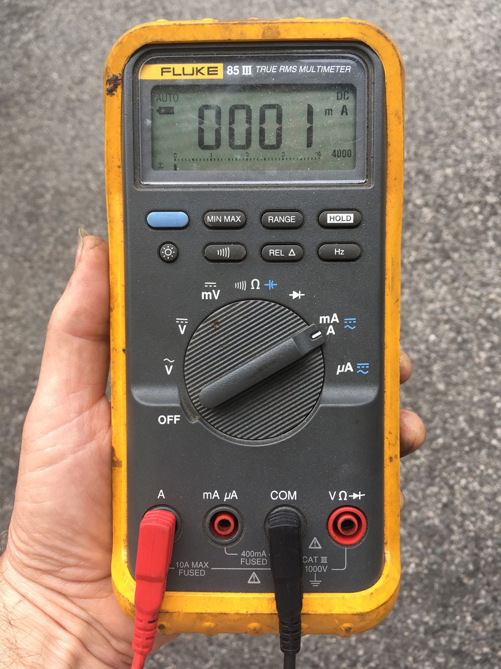
The image below demonstrates measuring the current of a small fan removed from a car for clarity.
- Circuit Setup: A battery’s positive terminal is connected to the fan’s positive terminal. The fan’s negative terminal is connected to the multimeter’s red lead (in current mode). The multimeter’s black lead is then connected to the battery’s negative terminal, completing the series circuit.
- Reading: In this example, the meter is showing approximately 5 amps.
Finding Parasitic Drains: The Key Application of Amp Draw Checks
The most practical and common use for checking amp draw is to diagnose parasitic drains. A parasitic drain is an unwanted electrical current draw that occurs when the car is turned off and should be in a resting state. These drains can slowly discharge your battery, leading to a dead battery, especially if the car sits for extended periods.
To check for a parasitic drain and identify its source, you need to measure the total current draw from the battery when everything is off. The multimeter needs to be connected in series between the negative battery terminal and the car’s chassis ground, measuring all current leaving the battery.
Traditional Fuse Pulling Method:
The classic method to pinpoint a parasitic drain involves:
- Connect the multimeter in series between the negative battery terminal and the car’s ground (as described above).
- Observe the initial current reading. This is your total parasitic draw.
- Start pulling fuses one by one. After removing each fuse, check the multimeter reading.
- Identify the culprit fuse: When you pull a fuse and the amp draw reading drops significantly, you’ve found the circuit containing the parasitic drain. Consult your car’s fuse box diagram to determine which components are on that circuit.
Challenges with Modern Vehicles:
While fuse pulling works on older cars with simpler electrical systems, it can be more complex on modern vehicles due to:
- Numerous Fuses: Modern cars have many more fuses, making the process time-consuming.
- Complex Modules: Electronic control modules (ECMs), body control modules (BCMs), and other modules are common. These modules often control multiple circuits and can be powered by more than one fuse, making isolation difficult.
- Module Sleep Time: Modern car modules often take time to “go to sleep” and reach their low-power standby state. This can range from 5 to 45 minutes after the car is turned off. Simply disconnecting the battery to switch your multimeter to a more sensitive range can reset this sleep timer, making accurate parasitic drain diagnosis challenging.
The Battery Disconnect Switch Trick for Accurate Parasitic Drain Testing
To overcome the module sleep time issue and accurately measure parasitic drain, use a battery disconnect switch installed on the negative battery post. Here’s the improved procedure:
- Install a Battery Disconnect Switch: Install a battery disconnect switch on the negative battery post for easy circuit interruption.
- Initial High-Amperage Setup: Configure your multimeter to measure current on the high-amperage (10A) setting.
- Connect Battery and Turn Everything Off: Turn the disconnect switch to the “ON” position (connecting the battery). Ensure everything in the car is turned off – lights, radio, accessories, USB chargers, etc. Close all doors to ensure dome lights are off.
- Connect Meter Across the Switch: Connect your multimeter across the battery disconnect switch terminals (between the negative battery post and the ground cable connection on the switch). Current will now flow through both the switch and the meter.
- Disconnect Battery with Switch: Quickly flip the battery disconnect switch to the “OFF” position. This forces all current to flow through the multimeter. Crucially, do not turn anything on or start the car! Starting the car will draw hundreds of amps and instantly overload your multimeter in current mode.
- Read the High-Amperage Reading: Observe the current reading on the multimeter in the high-amperage range. In a normal vehicle with everything off, the parasitic drain should be significantly less than 10A.
- Switch to Low-Amperage Range (Without Resetting Modules): If the reading is low enough (e.g., less than 300mA), you can switch to the more sensitive low-amperage range for a more precise measurement without interrupting power and resetting module timers:
a. Reconnect Battery Briefly: Flip the battery disconnect switch back to “ON” momentarily to reconnect the battery and bypass the meter.
b. Change Meter to Low-Amperage Setting: Quickly reconfigure your multimeter to the low-amperage (mA or µA) setting.
c. Disconnect Battery Again with Switch: Flip the battery disconnect switch back to “OFF,” forcing current to flow through the meter in the sensitive range. - Read Low-Amperage Reading: Observe the more precise parasitic drain reading on the low-amperage setting.
Interpreting Parasitic Drain Readings:
- Acceptable Drain: On a modern car with electronic modules, a parasitic drain of around 50-70 milliamps (mA) is often considered acceptable.
- Ideal Drain: A drain below 30mA is even better and indicates a very minimal parasitic load.
- Excessive Drain: Readings significantly higher than 70mA (e.g., hundreds of milliamps or amps) point to a problem that needs to be investigated and repaired to prevent battery drain.
Current Clamp Meters: An Alternative (But Consider Accuracy)
Current clamp meters offer a non-contact method to measure current. These meters have hinged jaws that clamp around a wire, inductively sensing the magnetic field created by current flow without needing to break the circuit.
- Advantages: Convenient and safe as you don’t need to interrupt the circuit.
- Considerations for Parasitic Drain Diagnosis:
- DC Current Measurement: Ensure the clamp meter can measure DC current (used in cars), as many are designed primarily for AC current (household wiring).
- Accuracy at Low Currents: For parasitic drain diagnosis, you need accuracy in the milliamp range (around 10mA resolution). Affordable clamp meters may not be accurate enough at these low current levels. High-accuracy DC clamp meters for automotive diagnostics can be expensive.
Unless you are a professional technician frequently diagnosing parasitic drains, investing in a high-precision DC clamp meter might not be necessary. The multimeter method with a battery disconnect switch is often sufficient and more cost-effective for DIYers.
Beyond Amp Draw: Voltage Drop Testing
While checking amp draw helps find parasitic drains and understand current flow, remember that “a circuit either works or it doesn’t” is not always the case. “High resistance failures” can occur, where increased resistance in a circuit reduces current flow and causes malfunctions without completely breaking the circuit. To diagnose these issues, you need to perform a voltage drop test, which we will cover in a future guide.
By mastering how to check amp draw with a multimeter, you gain a powerful tool for automotive electrical troubleshooting, especially for diagnosing battery drain issues. Remember to always prioritize safety, understand your multimeter’s settings, and use the techniques outlined here to accurately measure current and keep your car running smoothly.