Wiring diagrams are essential tools for anyone working with electrical systems, from automotive repair professionals to DIY enthusiasts. As a content creator for keyfobprog.com and an automotive repair expert, I understand the critical role wiring diagrams play in diagnosing and fixing electrical issues. This article delves into the world of wiring diagrams, providing clear Examples Of Wiring Diagrams and explaining their importance in various applications. We’ll explore different types of wiring diagrams, common symbols, and how to effectively use them for troubleshooting and repair.
What is a Wiring Diagram and Why Are Examples Important?
A wiring diagram is a visual roadmap of an electrical circuit. It uses symbols and lines to represent components and their connections, illustrating how electricity flows within a system. Think of it as the blueprint for your car’s electrical system or any electronic device. Instead of trying to decipher a complex tangle of wires, a wiring diagram provides a clear, organized representation of the circuit.
Examples of wiring diagrams are crucial because they demonstrate the practical application of these diagrams. Seeing real-world examples helps you understand how symbols translate into actual components and connections. By studying various examples, you can learn to interpret different diagram styles and gain confidence in using them for your own projects or repairs.
The Versatility of Wiring Diagrams: Usage Across Industries
Wiring diagrams are not limited to automotive repair. Their clarity and systematic approach make them invaluable in numerous fields:
- Automotive Technicians: Diagnosing electrical faults, installing aftermarket accessories, and repairing complex wiring harnesses in vehicles.
- Electricians: Planning electrical installations in buildings, troubleshooting household circuits, and wiring industrial machinery.
- Electronics Engineers: Designing circuits for electronic devices, documenting circuit layouts, and debugging prototypes.
- HVAC Technicians: Understanding the wiring of heating, ventilation, and air conditioning systems for installation and repair.
- DIY Enthusiasts: Working on home automation projects, car audio installations, and basic electronics repairs.
Wiring Diagrams vs. Schematic Diagrams vs. Pictorial Diagrams
While all three diagram types deal with electrical circuits, they serve different purposes and present information in distinct ways. Understanding these differences is key to choosing the right diagram for your needs.
| Feature | Wiring Diagram | Schematic Diagram | Pictorial Diagram |
|---|---|---|---|
| Focus | Physical connections and component location | Circuit function and logical operation | Highly detailed visual representation of components |
| Symbol Abstraction | Simplified shapes for components | Abstract, standardized symbols for components | Realistic drawings or photos of components |
| Line Representation | Wires and physical connections between components | Flow of current and circuit logic | Physical wires and their paths |
| Complexity | Can range from simple to complex, showing detail | Generally simpler, focusing on functionality | Often complex and visually cluttered |
| Best Used For | Installation, troubleshooting physical wiring | Circuit design, understanding circuit operation | Initial visual identification, rarely used in practice |


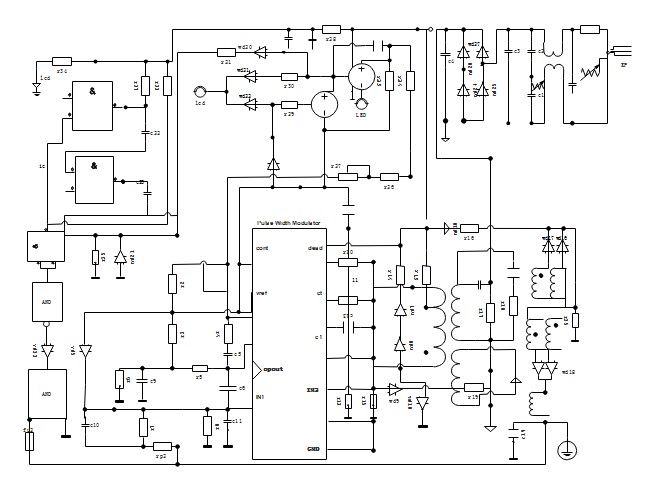

Alt Text: Schematic diagram example showing a 4-bit counter circuit, illustrating abstract symbols and logical connections.
Schematic diagrams, like the 4-bit counter example above, prioritize the function of the circuit. They use abstract symbols to represent components and lines to show the logical flow of electricity, not necessarily the physical layout.
Example of a Pictorial Diagram: Doorbell Wiring (wikimedia)
Alt Text: Pictorial diagram example illustrating doorbell wiring with detailed component drawings and wire representations, emphasizing visual detail.
Pictorial diagrams, on the other hand, aim for a highly visual, almost photographic representation. While they can be helpful for initial identification of components, their complexity often makes them less practical for troubleshooting or detailed work compared to wiring diagrams. As you can see in the doorbell wiring pictorial diagram, the level of detail can be overwhelming and less efficient for practical applications.
Decoding Wiring Diagrams: Essential Symbols
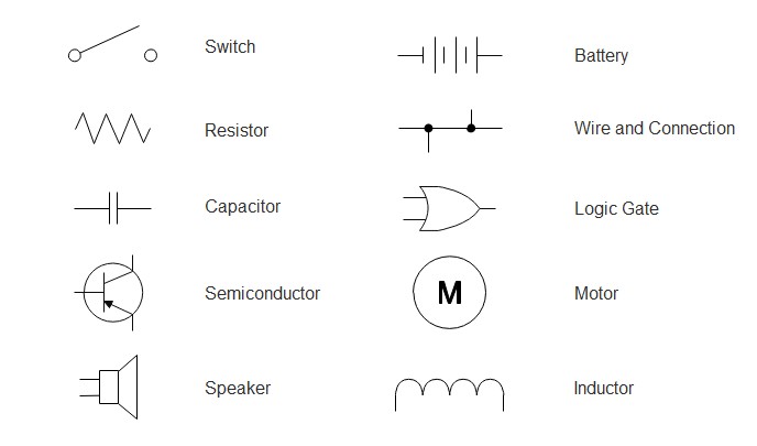
To effectively use wiring diagrams, understanding common symbols is crucial. These standardized symbols ensure that anyone familiar with electrical diagrams can interpret them, regardless of the specific application. Here are ten essential circuit symbols you’ll frequently encounter:
Alt Text: Chart showcasing common wiring diagram symbols including switch, wires, battery, resistor, capacitor, motor, speaker, inductor, logic gate, and semiconductor, essential for understanding electrical diagrams.
- Switch: Controls the flow of current in a circuit. Various switch types exist (push-button, toggle, etc.), but the general symbol represents the function of opening or closing a circuit.
- Wires: Represent electrical conductors connecting components. Diagrams differentiate between joined wires (indicated by a dot at the junction) and wires that cross but are not connected.
- Battery/Cell: The power source for the circuit, providing voltage. A battery symbol typically shows multiple cells connected in series.
- Resistor: Limits current flow in a circuit, controlling voltage and current distribution. Different symbols may represent fixed or variable resistors.
- Capacitor: Stores electrical energy in an electric field. Symbols distinguish between polarized and non-polarized capacitors.
- Motor: Converts electrical energy into mechanical motion. Essential in automotive systems for various functions like window operation, fan control, and more.
- Speaker: Converts electrical signals into audible sound waves. Found in car audio systems and warning systems.
- Inductor: Stores energy in a magnetic field when current flows through it. Used in filtering circuits and energy storage.
- Logic Gate: Fundamental building blocks of digital circuits, performing logical operations (AND, OR, NOT, etc.) on electrical signals. Used in complex electronic control units (ECUs) in vehicles.
- Semiconductor (Diode): Allows current to flow in only one direction. Diodes and transistors (also semiconductors) are crucial components in modern electronics and automotive systems.
Step-by-Step Guide: How to Read a Wiring Diagram
Reading a wiring diagram is a skill that develops with practice. Here’s a step-by-step approach to get you started:
Step 1: Symbol Recognition: Familiarize yourself with the basic electrical symbols. Refer to symbol charts and practice identifying them in different diagrams. Understanding symbols is the foundation of diagram interpretation.
Step 2: Trace the Lines and Connections: Lines represent wires. Follow the lines to see how components are interconnected. Pay attention to junctions (dots) indicating connected wires and crossings where wires pass without connection. Color-coding, if present, can further clarify wire identification (refer to the diagram’s legend).
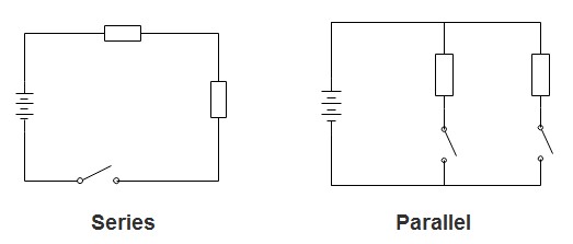
Step 3: Understand Circuit Types (Series and Parallel):
- Series Circuit: Components are connected in a single path. Current flows sequentially through each component. If one component fails, the entire circuit breaks.
- Parallel Circuit: Components are connected along multiple paths, each directly to the power source. Each component receives the same voltage. If one path breaks, others may still function.
Alt Text: Image illustrating wiring diagram line junctions, showing a dot for connected wires and a jump for wires crossing without connection.
Alt Text: Diagram comparing series and parallel circuits, highlighting current and voltage flow differences and component arrangement.
Step 4: Identify Input and Output: Determine the power source (battery, power supply) and the output devices (lights, motors, speakers). Trace the flow of current from input to output to understand the circuit’s operation.
Step 5: Practice with Examples of Wiring Diagrams: Start with simple diagrams and gradually progress to more complex ones. Analyzing examples of wiring diagrams is the most effective way to improve your reading skills.
Examples of Wiring Diagrams: Practical Applications
Let’s explore some practical examples of wiring diagrams to solidify your understanding and showcase their diverse applications:
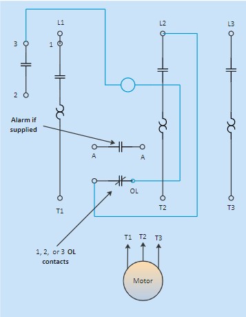
Example 1: Motor Starter Wiring Diagram
Motor Starter Wiring Diagram Example
Alt Text: Example of a motor starter wiring diagram, illustrating component placement and connections for motor control circuits, essential in industrial and automotive applications.
This diagram illustrates a motor starter circuit. It shows how components like relays, contactors, and overload protection devices are wired together to control an electric motor. Understanding motor starter wiring diagrams is crucial for automotive technicians working on electric vehicle drive systems or auxiliary motor controls.
Example 2: Home Electrical Wiring Plan
Home Electrical Wiring Plan Example
Alt Text: Example of a home electrical wiring plan, detailing internal and external wiring, power outlets, and circuit layouts for residential electrical systems.
This example demonstrates a comprehensive home electrical wiring plan. It maps out the wiring for lights, outlets, and appliances within a house. While primarily for electricians, understanding these diagrams can help anyone grasp the basic principles of electrical distribution and circuit layout.
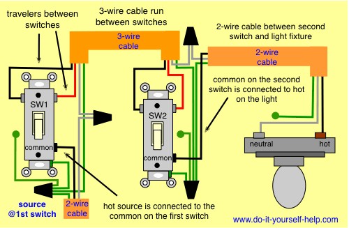
Example 3: 3-Way Switch Wiring Diagram
Alt Text: Wiring diagram example of a 3-way switch circuit, showing how two switches control a single light from different locations, commonly used in homes and vehicles.
This diagram shows a 3-way switch circuit, allowing you to control a light from two different locations. This configuration is common in homes (hallways, staircases) and also finds applications in automotive interior lighting and accessory control.
Example 4: Harness Wiring Diagram
Harness Wiring Diagram Example
Alt Text: Example of a harness wiring diagram, illustrating wire connections within a wiring harness, crucial for automotive and aerospace electrical systems.
Harness wiring diagrams are essential in automotive and aerospace industries. They detail how individual wires are bundled and connected within a wiring harness, ensuring organized and reliable electrical connections within a vehicle.
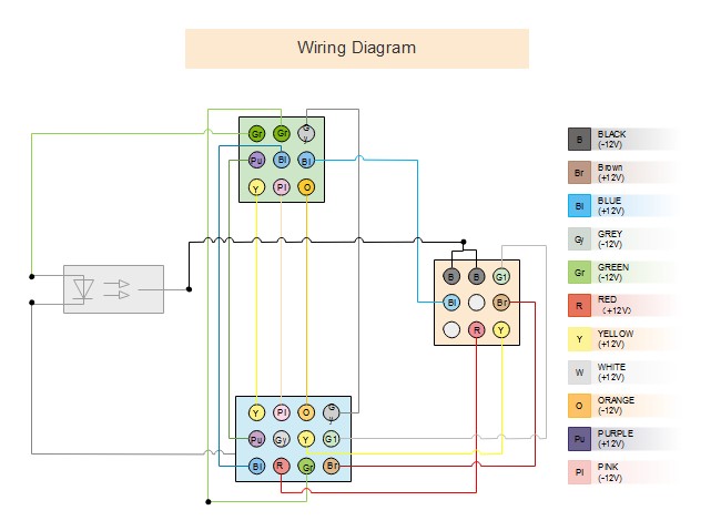
Example 5: Electrical Wiring Diagram (General)
General Electrical Wiring Diagram Example
Alt Text: Example of a general electrical wiring diagram, showcasing wire connections and physical layout of an electrical system, applicable to various electrical and electronic systems.
This is a more general example of an electrical wiring diagram, highlighting the wire connections and component layout in a system. It serves as a basic template applicable to various electrical and electronic projects.
Example 6: Semiconductor Electron Diagram (Conceptual)
Semiconductor Electron Diagram Example
Alt Text: Conceptual diagram of semiconductor electrons, illustrating the basic structure of semiconductor materials used in electronic components.
While not a traditional wiring diagram, this semiconductor electron diagram provides a visual representation of the materials underlying many electronic components used in wiring diagrams. Understanding semiconductors is crucial for advanced electrical work.
Software Tools for Creating Wiring Diagrams
Creating wiring diagrams by hand can be time-consuming and prone to errors. Software tools like EdrawMax streamline the process, offering libraries of symbols, templates, and automated features.
EdrawMax offers:
- Extensive Symbol Library: A vast collection of electrical and electronic symbols, ensuring accurate and standardized diagrams.
- Pre-drawn Templates: Ready-made templates for various wiring diagram types, saving time and effort.
- User-Friendly Interface: Drag-and-drop functionality and intuitive tools make diagram creation accessible to users of all skill levels.
- Cross-Platform Compatibility: Available on Windows, macOS, Linux, and web-based platforms for flexibility.
- Export and Sharing Options: Supports exporting diagrams in various formats (Visio, PDF, images) and sharing online.
Free Download Free Download Free Download
Conclusion: Mastering Wiring Diagrams Through Examples
Wiring diagrams are indispensable tools for anyone working with electrical systems. By providing clear visual representations of complex circuits, they simplify troubleshooting, installation, and design tasks. This article, through numerous examples of wiring diagrams, has aimed to demystify these essential tools and empower you to understand and utilize them effectively.
From automotive repair to home electrical projects, mastering wiring diagrams opens up a world of possibilities. Start by familiarizing yourself with common symbols, practice reading different diagram types, and leverage software tools to create your own diagrams. With dedication and the help of readily available examples of wiring diagrams, you can confidently navigate the intricacies of electrical systems.
Expert Tip: When creating or reading wiring diagrams, always prioritize clarity and accuracy. A well-drawn and correctly interpreted diagram is the key to successful electrical work. Pay attention to detail, use standardized symbols, and ensure your diagrams are easy to understand for yourself and others.
Related Resources
Wiring Diagram Software
What is a Floor Plan?
Circuit Diagram Maker