Maintaining your Volkswagen Jetta is crucial for its longevity and performance. A key aspect of this maintenance involves understanding and addressing issues within its electrical system. Fuses play a vital role in protecting your car’s electrical circuits from overloads. If you’re experiencing electrical problems in your 2011 Volkswagen Jetta, a blown fuse might be the culprit. This guide provides you with detailed fuse box diagrams and fuse layouts specifically for the 2011 Volkswagen Jetta, helping you diagnose and resolve electrical issues effectively.
Passenger Compartment Fuse Box
Fuse Box Location
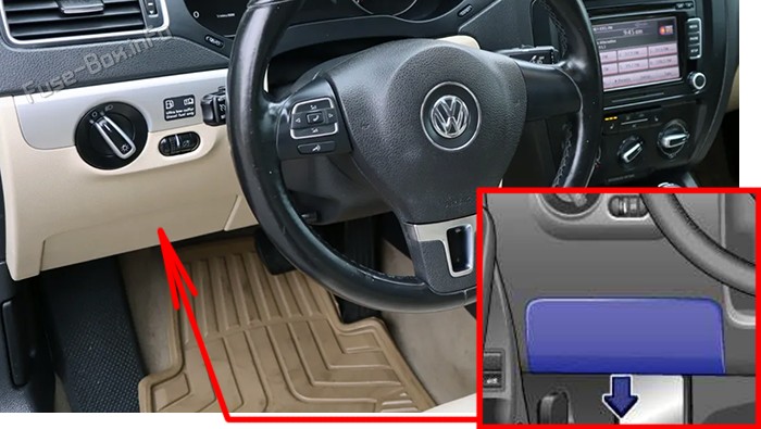
The primary fuse box inside your 2011 Volkswagen Jetta is conveniently located within the passenger compartment. To access it, you’ll need to find the cover on the driver’s side dashboard. Gently pull the lower edge of the cover in the direction indicated by the arrow, and then carefully remove it from the bottom. Inside the cover, you’ll also find a set of plastic tweezers. These are designed to assist in the safe removal and insertion of fuses, making the process easier and preventing damage to the fuses or your fingers.
Fuse Box Diagram
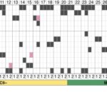
Below is the fuse assignment chart for the instrument panel fuse box in your 2011 Volkswagen Jetta. This diagram outlines each fuse location, its amperage, and the component or system it protects. Understanding this layout is essential for quickly identifying and replacing any blown fuses.
| № | Amps | Function/Component |
|---|---|---|
| F1 | 10A | Left washer nozzle heater, Right washer nozzle heater |
| F2 | 5A | Electronic steering column lock control module |
| F3 | 10A | Instrument cluster control module |
| F4 | 2A | Telephone Transceiver, Compass magnetic field sensor (vehicles equipped with Start/Stop) |
| F5 | 7.5A | Left rear fog lamp bulb |
| F6 | 10A | Vehicle electrical system control module (interior lamp), Rearview camera (from 2014) |
| F7 | 5A | Fog lamp relay, Instrument panel and switch illumination dimmer switch, License plate lamp, Vehicle electrical system control module |
| F8 | 7.5A | Windshield and headlamp washer pump switch, Windshield washer pump, Vehicle electrical system control module |
| F9 | 5A | Airbag control module, Front passenger airbag “disabled” indicator lamp, Passenger occupant detection system control module |
| F10 | 10A | Right steering column switch |
| F11 | 10A | Left front headlamp (HID headlamp) |
| F12 | 10A | Right front headlamp (HID headlamp) |
| F13 | 5A | Automatic dimming interior rearview mirror, Light recognition sensor, Parking aid control module, Air quality sensor, High pressure sensor, Climatronic control module, Tire pressure monitoring button, ASR/ESP button, Back-up lamp switch, Start/Stop mode switch, Mirror adjusting switch, Exterior rearview mirror heating switch, AC compressor control module (Engine code CNLA), Cornering lamp and headlamp range control module |
| F14 | 10A | Left steering column switch, ABS control module, Light switch, Airbag spiral spring/return spring with slip ring, Fuel pump control module, Towing recognition control module, Voltage stabilizer, Converter with socket, 12V-230V, Data bus on board diagnostic interface, Instrument cluster control module, Selector lever sensor system control module, Tiptronic switch, Power steering control module, Oil level thermal sensor, Hybrid battery unit (Engine code CNLA), Electric drive power and control electronics (Engine code CNLA) |
| F15 | 10A | 16-pin connector (diagnostic connection), Instrument panel and switch illumination dimmer switch, Headlamp range control adjuster, Fresh air blower relay, Mass airflow sensor, Positive crankcase ventilation heating element, Structure borne sound control module, Left front headlamp, Left headlamp beam adjustment motor, Right front headlamp, Right headlamp beam adjustment motor, Vehicle electrical system control module |
| F16 | 10A | Auxiliary engine coolant pump relay, Fuel pump control module, Engine control module, Electric drive button (Engine code CNLA) |
| F17 | 10A | Anti-theft alarm system horn (Running change), Anti-theft alarm system interior sensor (Running change), Anti-theft alarm system alarm (Running change) |
| F18 | 15A | Left front headlamp, Left low beam headlamp bulb (vehicles with China equipment) |
| F19 | 15A | Right front headlamp, Right low beam headlamp bulb (vehicles with China equipment) |
| F20 | 10A | Ignition/starter switch, Tiptronic switch, Automatic transmission control module, Selector lever sensor system control module, Climatronic control module, Auxiliary engine coolant heater radio frequency receiver |
| F21 | 15A | Vehicle electrical system control module, Dual tone horn relay, High tone horn, Low tone horn |
| F22 | 20A | Ignition/starter switch, Converter box, Interior monitoring sensor, Alarm horn relay, Alarm horn, Dual tone horn relay (2010-1011) |
| F23 | 10A | Vehicle electrical system control module, 16-pin connector (diagnostic connection), Light switch, Rain/light recognition sensor, Compass magnetic field sensor (vehicles without Start/Stop) |
| F24 | 10A | Vehicle electrical system control module, Access/start authorization control module |
| F25 | 15A | Automatic transmission control module, Selector lever sensor system control module, Multifunction switch |
| F26 | 15A | Brake system vacuum pump |
| F27 | 1A | Airbag spiral spring/return spring with slip ring |
| F28 | 40A | Auxiliary heater operation relay |
| F29 | 1A | Vehicle electrical system control module, Ignition/starter switch, Converter box |
| F30 | 20A | Cigarette lighter, 12V socket, 12V socket 2, Blocking diode |
| F31 | 30A | Light switch |
| F32 | 20A | Light switch |
| F33 | 40A | Heater/heat output switch, Fresh air blower relay, AC control module, Fresh air blower switch |
| F34 | 15A | Left high beam headlamp bulb, Right high beam headlamp bulb, Instrument cluster control module |
| F35 | 10A | Steering column electronics control module, Data bus on board diagnostic interface, Instrument cluster control module (2010-2011), Signal horn activation (2010-2012) |
| F36 | 25A | Vehicle electrical system control module |
| F37 | 15A | Left front headlamp, Left daytime running lamp bulb |
| F38 | 15A | Right front headlamp, Right daytime running lamp bulb |
| F39 | 20A | Low beam relay |
| F40 | 15A | Towing recognition control module |
| F41 | 15A | Towing recognition control module |
| F42 | 20A | Towing recognition control module |
| F43 | 30A | Front passenger door control module |
| F44 | 25A | Rear window defogger relay, Rear window defogger, Vehicle electrical system control module |
| F45 | 30A | Driver door control module, Front passenger door control module (vehicles with China equipment) |
| F46 | 30A | Left rear door control module, Right rear door control module |
| F47 | 15A | Fuel pump control module, Fuel pump relay, Fuel primer relay |
| F48 | 20A | Vehicle electrical system control module |
| F49 | 40A | Fresh air blower, Climatronic control module, A/C control module |
| F50 | 30A | Front seat heating control module |
| F51 | 20A | Sunroof control module |
| F52 | 20A | Dual tone horn relay (2010-2012), Headlamp Washer Relay (2013-2017), Headlamp washer pump (2013-2017) |
| F53 | 15A | Front seat heating control module (2010-2012), Driver seat lumbar support adjustment switch (2013-2017) |
| F54 | 15A | Fog lamp relay |
| F55 | 20A | Light switch, Left steering column switch |
| F56 | 10A | Hybrid battery unit (Engine code CNLA), Electric drive power and control electronics (Engine code CNLA) |
| F57 | 15A | Radio, Radio/Navigation Display Control Module |
| F58 | 1A | Telephone Transceiver (2010-2011), Converter with socket 12V-230V |
| F59 | 15A | Amplifier (2010-2012), Fan activation relay (Engine code CNLA) (2013-2017), Battery fan 1 (Engine code CNLA) (2013-2017) |
| F60 | 30A | Auxiliary heater control module |
| – | 20A | Driver power seat adjustment circuit breaker 1 (located above relay carrier) |
Relays in the Passenger Compartment
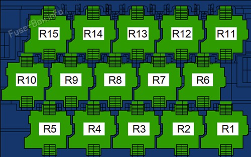
Located above the fuse panel in the passenger compartment is the relay carrier. Relays are electrical switches that control higher current circuits, and they are just as important as fuses in managing your Jetta’s electrical system. The 2011 Volkswagen Jetta utilizes different relay carriers depending on the production date.
15-Pin Relay Carrier (for 2010-2011 models):
This configuration is typically found in early 2011 and 2010 models of the Volkswagen Jetta.
| № | Description |
|---|---|
| R1 | Converter box (E-Box Low, (AWO)) |
| R2 | Fresh air blower relay |
| R3 | Auxiliary heater operation relay -J485- (449) |
| R4 | Fuel Pump Relay, Engine Component Power Supply Relay, Auxiliary engine coolant pump relay |
| R5 | Low beam relay (E-Box Low, (AWO)) |
| R6 | Fresh air blower relay |
| R7 | Terminal 75 power supply relay 1 |
| R8 | Dual tone horn relay, Headlamp washer relay |
| R9 | Power Supply Relay (terminal 50) -J682- (643) |
| R10 | Terminal 15 power supply relay 2 -J681- (643) |
| R11 | Rear window defogger relay -J9- (449) |
| R12 | Fuel pump relay 2, Heat resistance relay, Cold start injector relay, Fuel primer relay |
| R13 | Power Supply Relay (terminal 50) |
| R14 | Terminal 15 power supply relay |
| R15 | Fog lamp relay |
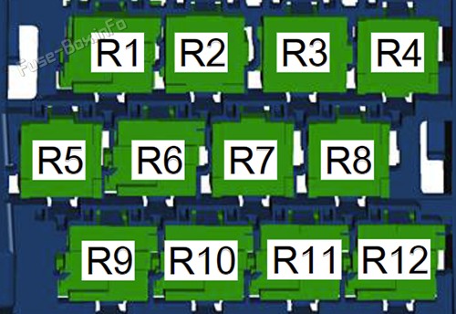
12-Pin Relay Carrier (for 2012-2017 models, but potentially late 2011 models):
Later 2011 models and onward may use this 12-pin relay carrier configuration. Always verify which carrier is in your vehicle.
| № | Description |
|---|---|
| R1 | Dual tone horn relay, Alarm horn relay (USA and Mexico, E-Box Low), Headlamp washer relay |
| R2 | Power Supply Relay (terminal 50), Starter relay 2, Driver power window opening relay (E-Box high, since 2013), Driver power window closing relay (E-Box high, since 2013) |
| R3 | Cold start injector relay (since 2013), Secondary air injection pump relay (CNLA), Fuel pump relay 2, Front passenger power window opening relay (E-Box high, since 2013), Heat resistance relay, Front passenger power window closing relay (E-Box high, since 2013) |
| R4 | Coolant circulation pump relay (up to 2012), Fuel Pump Relay, Auxiliary engine coolant pump relay, Fuel primer relay, Engine Component Power Supply Relay (E-Box high, since 2013) |
| R5 | Terminal 75 power supply relay 1 (up to 2012) |
| R6 | Power Supply Relay (terminal 50), Starter relay 1 |
| R7 | Terminal 15 power supply relay (E-Box Low), Auxiliary heater operation relay (E-Box high), Power window relay (E-Box high, since 2013) |
| R8 | Low beam relay (E-Box Low), Rear window defogger relay (E-Box high) |
| R9 | Terminal 15 power supply relay 2 |
| R10 | Terminal 75 power supply relay 1 |
| R11 | Fog lamp relay (E-Box Low), Fresh air blower relay (E-Box high), Fan activation relay (hybrid) |
| R12 | Converter box (E-Box Low) |
Engine Compartment Fuse Box
Fuse Box Location
For components under the hood, your 2011 Volkswagen Jetta has a second fuse box located in the engine compartment. To access this fuse box, locate the black plastic housing, typically near the battery or engine control unit. Unlock the fuse box cover by moving the release tabs in the direction of the arrows usually molded into the plastic. Once unlatched, lift the cover upwards to remove it, exposing the fuses and relays inside.
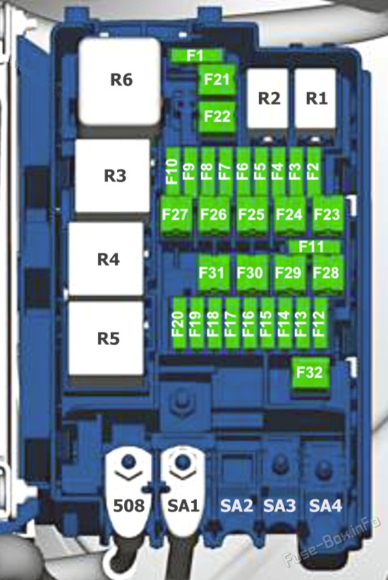
Fuse Box Diagram
The following table details the fuse assignments for the engine compartment fuse box in your 2011 VW Jetta. This diagram is critical for diagnosing issues related to engine components, and other systems located in the engine bay.
| № | Amps | Function/Component |
|---|---|---|
| F1 | – | Not used |
| F2 | 10A/15A | Engine control module, Engine component power supply relay |
| F3 | 5A/10A | Coolant fan control module, Relay for low heat output, Relay for high heat output |
| F4 | 5A/10A/15A | Oxygen sensor heater, Heater for oxygen sensor 1 after catalytic converter, High temperature circuit coolant pump (Engine codes CNLA, CRJA), Low temperature circuit coolant pump |
| F5 | 5A/10A/20A | Oxygen sensor heater, Oxygen sensor 2 heater (Engine codes CNLA, CRJA), Leak detection pump, Wastegate bypass regulator valve, EGR cooler switch-over valve, Positive crankcase ventilation heating element, Mass airflow sensor (Engine code CFFB), Vacuum pump relay, Brake system vacuum pump |
| F6 | 5A/10A/15A/20A | Leak detection pump, EVAP canister purge regulator valve 1, Tank switch-off valve, Secondary air injection pump relay |
| F6 | 5A/10A/15A | Water pump, Auxiliary heater heating element, Relay for low heat output, Relay for high heat output |
| F7 | 20A | Petrol: Ignition coil 1~4 with power output stage |
| F7 | 5A | Diesel: Fuel pressure regulator valve, Fuel metering valve |
| F8 | 10A | Throttle valve control module, Wastegate bypass regulator valve, EVAP canister purge regulator valve 1, Camshaft adjustment valve 1, Turbocharger recirculation valve, Intake manifold runner control valve, Exhaust camshaft adjustment valve 1 (Engine codes CNLA, CRJA), Oil pressure regulation valve (Engine codes CNLA, CRJA), Decoupler pressure actuator (Engine codes CNLA, CRJA), Refrigerant cut-off valve (Engine codes CNLA, CRJA) |
| F9 | 5A/15A | Secondary air injection sensor 1, Secondary air injection sensor 2, Automatic glow time control module, Fuel pump relay 2, Fuel pump relay, EVAP canister purge regulator valve 1, Camshaft adjustment valve 1, Fuel pressure regulator valve, After-run coolant pump, Coolant circulation pump relay, Engine coolant circulation pump 2 |
| F10 | 5A | Brake lamp switch, Clutch position sensor, Auxiliary engine coolant pump relay, Brake booster relay (Engine codes CNLA, CRJA), Speed sensor |
| F11 | – | Not used |
| F12 | 5A | Ignition coil 1~4 with power output stage, After-run coolant pump |
| F13 | 5A/20A | Auxiliary engine coolant pump relay, Water pump, Brake booster relay (Engine codes CNLA, CRJA), Brake system vacuum pump (Engine codes CNLA, CRJA) |
| F14 | 5A | Engine control module, Main relay |
| F15 | 30A | Voltage stabilizer |
| F16 | 30A | ABS control module |
| F17 | 30A | DSG transmission Mechatronic |
| F18 | 20A | DSG transmission Mechatronic |
| F19 | 1A | Vehicle electrical system control module |
| F20 | 30A | Vehicle electrical system control module (AW0), Wiper/washer intermittent relay (AW1), Wiper motor change-over relay 1 (AW1), Wiper motor change-over relay 2 (AW1) |
| F21 | 50A | Secondary air injection pump motor |
| F22 | 40A | Auxiliary heater heating element |
| F23 | 40A | ABS control module |
| F24 | 50A | Towing recognition control module |
| F25 | 50A | Terminal 15 power supply relay, Terminal 15 power supply relay 2 |
| F26 | 50A/40A | Automatic glow time control module, Secondary air injection pump relay, Secondary air injection pump motor (Engine codes CNLA, CRJA) |
| F27 | 50A/60A | Coolant fan |
| F28 | 40A | Vehicle electrical system control module |
| F29 | 40A | Vehicle electrical system control module |
| F30 | 50A | Terminal 75 power supply relay 1 |
| F31 | 30A | Amplifier |
| F32 | 40A | Auxiliary heater heating element |
| 508 | Threaded connection (30) on the E-box | |
| SA1 | 200A | Without Hybrid system: Generator, With Hybrid system: Electric drive power and control electronics, Voltage converter |
| SA2 | – | Not used |
| SA3 | 80A | Steering |
| SA4 | 80A | Without Hybrid system: Interior terminal 30 power supply SC fuses |
| R1 | Wiper motor change-over relay 1 / Not used (AW0) | |
| R2 | Wiper motor change-over relay 2 / Not used (AW0) | |
| R3 | Main relay, Terminal 30 power supply relay, Fuel primer relay | |
| R4 | Relay for low heat output, Coolant circulation pump relay (Running change), Auxiliary engine coolant pump relay | |
| R5 | Relay for high heat output, Secondary air injection pump relay (gasoline), Brake booster relay (Hybrid, with auxiliary heater) | |
| R6 | Automatic glow time control module, Brake booster relay (Hybrid, without auxiliary heater) |
Troubleshooting and Fuse Replacement
When diagnosing electrical issues in your 2011 Volkswagen Jetta, always start by checking the fuses. A blown fuse is a common cause of malfunctions and is a simple fix. Use the provided fuse diagrams to locate the fuse related to the malfunctioning component.
Steps to check and replace a fuse:
- Identify the problem: Determine which electrical component is not working.
- Locate the correct fuse diagram: Use this guide to find the appropriate fuse box diagram for your Jetta.
- Find the fuse: Using the diagram, locate the fuse associated with the faulty component.
- Inspect the fuse: Remove the fuse using the tweezers and check if the wire inside is broken. A blown fuse will have a visible break in the wire.
- Replace the fuse: If the fuse is blown, replace it with a new fuse of the exact same amperage. Never use a fuse with a higher amperage, as this can damage the electrical system.
- Test the system: After replacing the fuse, check if the electrical component is now working correctly.
Important Notes:
- Always replace a blown fuse with one of the same amperage rating.
- If a fuse blows repeatedly, it indicates a more serious underlying electrical problem that requires professional diagnosis.
- Keep spare fuses of various amperages in your vehicle for emergencies.
Understanding the fuse layout of your 2011 Volkswagen Jetta is a valuable skill for any car owner. By using this guide, you can confidently troubleshoot and resolve minor electrical issues, saving time and money on unnecessary repairs. Regularly checking your fuses can also help prevent more significant electrical problems down the road, ensuring your Jetta remains reliable and safe.