Electrical diagrams, also known as wiring diagrams or schematics, are the roadmaps of automotive electrical systems. For anyone involved in car repair, from seasoned mechanics to DIY enthusiasts, understanding how to read these diagrams is an indispensable skill. They provide a visual representation of the complex network of wires, components, and connections that make up a vehicle’s electrical system, enabling efficient troubleshooting, accurate repairs, and confident modifications.
Without the ability to interpret electrical diagrams, diagnosing electrical issues becomes a time-consuming and often frustrating process of guesswork. These diagrams offer a structured and logical way to understand circuit functionality, component locations, and wiring paths. This guide will equip you with the knowledge to navigate and interpret electrical diagrams effectively, enhancing your diagnostic skills and repair precision in the automotive field. We’ll break down the essential elements, from basic symbols to advanced reading techniques, ensuring you can confidently trace circuits and resolve electrical problems.
Decoding Electrical Diagram Symbols: The Building Blocks
Just like learning the alphabet is crucial for reading text, understanding electrical symbols is the first step to reading electrical diagrams. These standardized symbols represent various electrical and electronic components. Familiarity with these symbols allows you to quickly identify components within a diagram and grasp their function in the circuit. Let’s explore some of the most common symbols you’ll encounter in automotive electrical diagrams.
Resistors
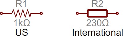
Resistors are fundamental components that control the flow of current in a circuit. In diagrams, they are typically represented by a zig-zag line or a rectangle (in international standards). Automotive applications of resistors are diverse, ranging from sensor circuits (like temperature and pressure sensors) to controlling current to LEDs in lighting systems.
Potentiometers and Variable Resistors
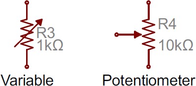
Variable resistors and potentiometers, often used in sensor circuits or adjustable controls, are represented by the standard resistor symbol with an added arrow. A variable resistor (rheostat) has two terminals and the arrow bisects the zig-zag. A potentiometer, with three terminals, uses the arrow as the third terminal, representing the wiper. These are common in circuits where adjustability or variable resistance based on sensor input is needed, such as throttle position sensors or volume controls.
Capacitors
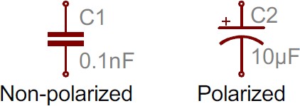
Capacitors store electrical energy and are crucial for filtering, smoothing, and timing circuits in automotive electronics, particularly within Engine Control Units (ECUs) and other electronic modules. Diagrams use two parallel lines to symbolize capacitors. A curved line on one side indicates a polarized capacitor (like electrolytic or tantalum types), which must be installed with correct polarity. Non-polarized capacitors use two straight parallel lines.
The curved plate in the polarized capacitor symbol typically denotes the cathode (negative terminal). Polarized capacitors in automotive systems are often used for filtering voltage supplies to sensitive electronics.
Inductors
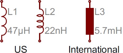
Inductors, also known as coils or chokes, are components that store energy in a magnetic field when current flows through them. They are often used in automotive circuits for filtering noise, in relay circuits, and in some types of sensors. The symbol for an inductor resembles a series of loops or curved bumps. In international symbols, a filled rectangle might also represent an inductor.
Relays and solenoids in automotive systems heavily rely on inductors to create a magnetic field that actuates mechanical movement.
Switches and Relays
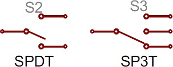
Switches and relays control the flow of current in a circuit, acting as electrical gates. A basic Single-Pole Single-Throw (SPST) switch, a fundamental type, is shown as two terminals with a line representing the switch actuator.
More complex switches like Single-Pole Double-Throw (SPDT) and Single-Pole Triple-Throw (SP3T) have additional “throws,” or positions, allowing them to direct current to different paths. Relays, which are electrically operated switches, often combine a coil symbol (inductor) with a switch symbol, indicating that energizing the coil will change the switch state.
In automotive diagrams, you’ll find switch symbols representing everything from simple light switches to complex ignition switches and relay controls for various systems like headlights, fuel pumps, and air conditioning.
Power Sources and Grounds
Power sources and grounds are essential for any electrical circuit. Diagrams use specific symbols to denote different types of power sources, such as batteries, DC voltage sources, and ground connections. Understanding these symbols is crucial for tracing power flow in a diagram.
DC and AC Voltage Sources
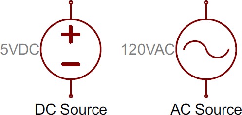
In automotive systems, Direct Current (DC) voltage sources, primarily batteries and the DC output from the charging system, are predominant. Symbols for DC voltage sources usually feature a circle with positive (+) and negative (-) signs inside, or parallel lines of unequal length (as seen with batteries). Alternating Current (AC) sources, less common in standard automotive DC systems but relevant in some hybrid/electric vehicle contexts or diagnostic equipment, are represented by a sine wave symbol within a circle.
Batteries
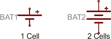
Batteries, the primary DC power source in vehicles, are typically depicted by pairs of parallel lines, with longer lines representing the positive terminal and shorter lines the negative. Multiple pairs indicate multiple cells in series, as in a car battery.
Voltage Nodes and Grounds
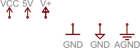
Voltage nodes and ground symbols simplify diagrams by representing common voltage levels and ground points without drawing extensive wiring. Positive voltage nodes like 12V, 5V, or Battery Voltage (B+) are often shown as an upward-pointing arrow or a labeled terminal. Ground, or chassis ground, is represented by one of several symbols, including three parallel lines decreasing in length, a downward-pointing arrow, or a triangle. These symbols indicate a connection to the vehicle’s chassis, which serves as the common ground reference point.
Advanced Component Symbols in Automotive Diagrams
Beyond the basic components, automotive electrical diagrams incorporate symbols for more specialized electronic components. Understanding these symbols is crucial for diagnosing issues in complex systems.
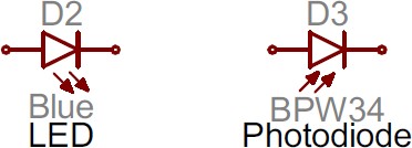
Diodes and LEDs
Diodes are semiconductor devices that allow current to flow in one direction only. They are symbolized by a triangle pointing towards a vertical line. The triangle side represents the anode (positive), and the line represents the cathode (negative). Light Emitting Diodes (LEDs), a type of diode that emits light when current passes through, are represented by the standard diode symbol with two arrows pointing away, indicating light emission.
Diodes in vehicles are used for rectification (converting AC to DC, as in alternators), voltage regulation, and preventing reverse current flow. LEDs are increasingly used for indicator lights and general illumination.
Transistors
Transistors are semiconductor devices used for switching and amplifying electronic signals and power. Two main types are Bipolar Junction Transistors (BJTs) and Metal-Oxide-Semiconductor Field-Effect Transistors (MOSFETs). Both types have distinct symbols, with variations for NPN/PNP BJTs and N-channel/P-channel MOSFETs.
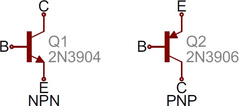
Bipolar Junction Transistors (BJTs)
BJTs have three terminals: Base (B), Collector (C), and Emitter (E). NPN and PNP types are differentiated by the direction of the arrow on the emitter. For NPN transistors, the arrow points away from the base (NPN: Not Pointing In). For PNP transistors, the arrow points towards the base.
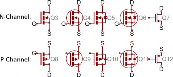
Metal-Oxide-Semiconductor Field-Effect Transistors (MOSFETs)
MOSFETs, also three-terminal devices (Gate (G), Drain (D), Source (S)), have symbols that vary slightly depending on the type (N-channel or P-channel) and depletion or enhancement mode. Generally, the symbol includes a vertical line for the drain and source, a line for the gate, and an arrow indicating the channel type. For N-channel MOSFETs, the arrow points inwards; for P-channel, it points outwards (N-channel: n is in).
Transistors are fundamental in modern automotive electronics, used in ECUs, sensor interfaces, and power control modules.
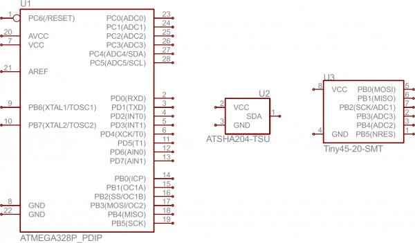
Integrated Circuits (ICs) and Logic Gates
Integrated Circuits (ICs) are complex circuits miniaturized onto a single chip. In diagrams, ICs are usually represented by rectangles with pins extending outwards. Each pin is labeled with a number and often a functional description. Due to their complexity and variety, ICs generally do not have specific symbols beyond this rectangular representation. Component identification relies heavily on the IC’s part number and function.
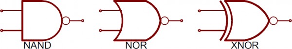
Logic Gates
Logic gates are fundamental building blocks of digital electronics, performing Boolean logic functions. Common logic gates include AND, OR, NOT, XOR, NAND, NOR, and XNOR. Each has a distinct symbol. In automotive ECUs and digital control systems, logic gates are used extensively for decision-making and control functions.
Miscellaneous Automotive Symbols
Beyond core electronic components, automotive diagrams include symbols for various other devices specific to vehicle systems.
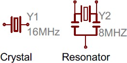
Crystals and Resonators
Crystals and resonators are used to generate precise timing signals, crucial for microcontroller operation in ECUs and other modules. Crystal symbols typically have two terminals, while resonators, which integrate capacitors, often have three.
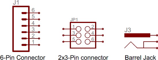
Connectors and Wiring Harnesses
Connectors are essential for joining wires and modules in automotive electrical systems. Symbols vary based on connector type, but often resemble stylized plugs or sockets. Wiring harnesses, representing bundles of wires, are indicated by groups of parallel lines. Understanding connector symbols helps in locating physical connectors in the vehicle.
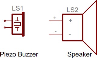
Motors, Solenoids, Speakers, and Relays
Symbols for motors, solenoids, speakers, and relays often incorporate coil symbols, reflecting their electromagnetic nature. Motors are usually shown as a circle with an “M” inside. Solenoids, similar to relays but designed for linear motion, may use relay-like symbols or specific solenoid symbols. Speakers are represented by a stylized speaker cone shape. Relays, as mentioned earlier, combine a coil and switch symbol.
Fuses and Circuit Breakers
Fuses and circuit breakers are safety devices that protect circuits from overcurrents. Fuse symbols typically resemble a zig-zag line enclosed in a rectangle or a simple line breaking in the middle. Circuit breakers may have similar symbols or more switch-like representations. PTC (Positive Temperature Coefficient) resistors, often used as resettable fuses, have a symbol combining a resistor symbol with a temperature indicator.
Name Designators and Values: Identifying Components Uniquely
Simply recognizing symbols isn’t enough; understanding component names and values is crucial for precise diagram interpretation. Each component in an electrical diagram is typically assigned a unique name and value, providing specific identification and characteristics.
Names and Values Explained
Values specify the electrical characteristic of a component. For resistors, it’s the resistance in ohms; for capacitors, capacitance in farads; for inductors, inductance in henries. For ICs, the value often refers to the IC’s part number or function. Crystals might list their frequency as their value. The value essentially defines the component’s operational parameter.
Names, also called reference designators, are alphanumeric codes that uniquely identify each component in the diagram. They usually start with one or two letters indicating the component type (R for resistor, C for capacitor, U for IC, etc.) followed by a number. For example, R1, R2, R3 would denote different resistors in the circuit. These names are vital for referencing specific components within the diagram and in accompanying documentation.
Standard prefixes for component names include:
| Name Identifier | Component |
|---|---|
| R | Resistors |
| C | Capacitors |
| L | Inductors |
| S | Switches |
| D | Diodes |
| Q | Transistors |
| U | Integrated Circuits |
| Y | Crystals/Oscillators |
While these are generally standardized, variations can exist. For example, ICs might be labeled “IC” or crystals as “XTAL.” Context and symbol recognition usually help clarify component identification.
Reading the Diagram: Nets, Nodes, and Circuit Flow
Once you’re familiar with symbols and naming conventions, the next step is to understand how components are interconnected in the diagram. This involves tracing nets, identifying nodes, and following circuit flow.
Nets, Nodes, and Labels: Connections and Pathways
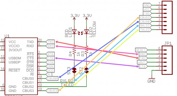
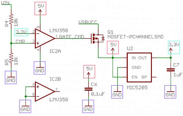
Nets, represented by lines in the diagram, illustrate the wiring connections between component terminals. Sometimes, nets are color-coded in diagrams to distinguish different types of wiring (e.g., power, ground, signal).
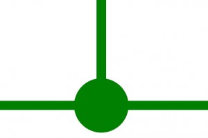
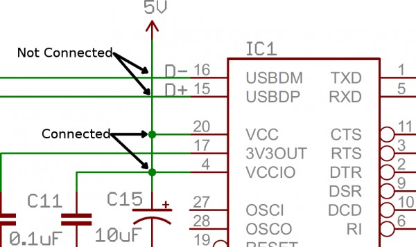
Junctions and Nodes: Wire Intersections
When wires intersect and are electrically connected, it’s called a junction, marked by a node – a small dot at the intersection point. Nodes clearly indicate where wires are joined. Absence of a node at a wire crossing implies no electrical connection; the wires simply pass over each other.
Net Names and Labels: Simplifying Complexity
To prevent diagrams from becoming cluttered with long wiring lines, especially in complex systems, nets are often labeled with names. Nets with the same name are assumed to be electrically connected throughout the diagram, even without a visible connecting line. Labels can be placed directly on the net line or as “tags” branching off the line.
Net names are typically descriptive, indicating the signal or voltage carried, like “Battery Voltage,” “Ground,” “Ignition Switch,” “CAN High,” etc. This labeling significantly simplifies reading complex diagrams by reducing visual clutter.
Tips for Efficiently Reading Automotive Electrical Diagrams
Reading automotive electrical diagrams effectively requires a strategic approach. Here are some helpful tips to enhance your diagram reading skills:
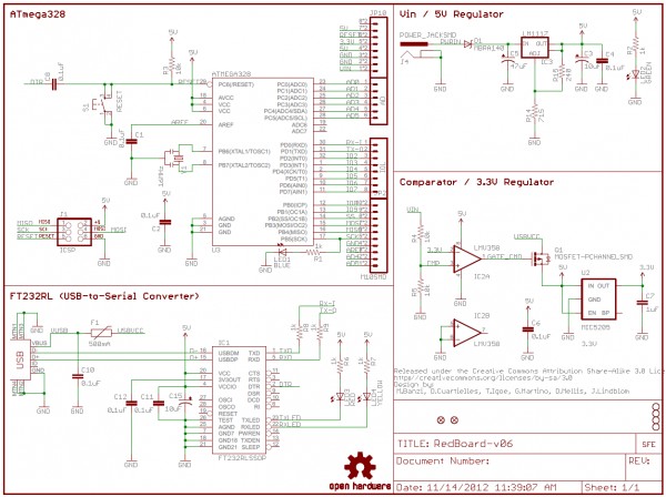
Identify System Blocks
Complex automotive diagrams are usually organized into functional blocks or sections representing different vehicle systems (e.g., engine management, braking system, lighting). Start by identifying these blocks. Look for system names or descriptions often located at the top or within sections of the diagram. Understanding the system you are working on provides context and simplifies navigation.
Recognize Voltage Nodes and Ground Points
Quickly locate voltage nodes (like Battery Voltage, 5V, etc.) and ground symbols. These are crucial reference points in the circuit. Ground points, especially, are frequently used and understanding their distribution is vital for tracing current paths and identifying grounding issues.
Utilize Component Lists and Pinouts
Automotive diagrams often come with component lists or parts lists, detailing the components used and their reference designators. Pinout diagrams, especially for ECUs and modules, show the function of each pin on a connector. Referencing these lists and pinouts alongside the diagram greatly aids in component identification and understanding module connections.
Trace Circuits Step-by-Step
When diagnosing a problem, trace the relevant circuit step-by-step, starting from the power source, through switches, relays, components, and finally to ground. Follow the nets, paying attention to nodes, labels, and component names. This systematic approach helps in understanding the circuit’s operation and pinpointing potential fault locations.
Consult Component Datasheets and Service Manuals
If you encounter unfamiliar components or need detailed information, refer to component datasheets or the vehicle’s service manual. Datasheets provide in-depth specifications and functional descriptions of components, while service manuals offer system-specific diagrams and diagnostic procedures.
Conclusion: Mastering the Language of Automotive Electrical Systems
Learning to read electrical diagrams is a foundational skill for anyone working with automotive electrical systems. It transforms complex wiring into understandable pathways, enabling efficient diagnostics and repairs. By mastering component symbols, understanding diagram conventions, and practicing circuit tracing, you gain the ability to confidently navigate and interpret these essential roadmaps of vehicle electronics. Consistent practice and application are key to proficiency. With this knowledge, you are well-equipped to tackle automotive electrical challenges with precision and expertise.
Further Resources for Electrical Diagram Mastery
To deepen your understanding and skills in reading electrical diagrams, consider exploring these resources:
- Vehicle-Specific Service Manuals: These manuals are invaluable, providing detailed diagrams and system descriptions for specific makes and models.
- Online Automotive Schematic Databases: Websites like Alldata, Mitchell OnDemand, and others offer access to vast databases of vehicle wiring diagrams.
- Electronics Tutorials and Courses: Online platforms like Coursera, Udemy, and Khan Academy offer courses on basic electronics and circuit analysis, which can enhance your understanding of diagram principles.
- Automotive Diagnostic Forums and Communities: Engaging with online communities of automotive technicians can provide practical insights and solutions for diagram interpretation and troubleshooting.
By continuously learning and applying these skills, you’ll become proficient in reading electrical diagrams, a critical asset for any automotive technician or enthusiast.