Potentiometers, often referred to as “pots,” are indispensable components in electronics, allowing for variable resistance control in a circuit. Whether you’re adjusting the volume on a car stereo, calibrating a sensor in an automotive system, or fine-tuning an electronic circuit, understanding how to wire a potentiometer is a fundamental skill. As a content creator for keyfobprog.com and an automotive repair specialist, I’m here to provide you with a comprehensive guide on potentiometer wiring, ensuring you can confidently integrate these versatile devices into your projects.
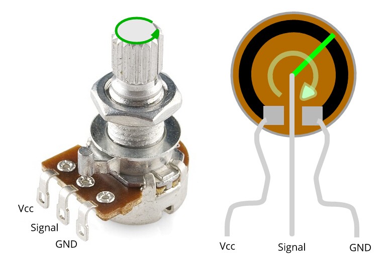
Potentiometers are essentially variable resistors with three terminals. They consist of a resistive element and a wiper that moves along this element. By changing the wiper’s position, you alter the resistance between the wiper terminal and the other two terminals. This capability makes them crucial for controlling voltage and current flow in a wide range of applications, from simple audio volume controls to complex sensor adjustments in automotive electronics. Their adaptability and ease of integration into circuits make potentiometers an essential tool in both basic and advanced electronic design.
In this guide, we’ll explore the different types of potentiometers, how to choose the right one for your project, and, most importantly, detailed instructions on how to wire a potentiometer correctly for optimal performance.
Exploring Different Types of Potentiometers
Potentiometers come in various forms, each designed for specific applications. Understanding these types is crucial when deciding how to wire a potentiometer and choosing the best one for your needs.
Linear Potentiometers
Linear potentiometers, or linear taper potentiometers, are characterized by a resistive element that changes uniformly as the wiper moves. This means that the resistance changes at a constant rate across the potentiometer’s range of motion. They are commonly used in applications where a consistent and proportional adjustment is needed, such as in lighting dimmers or basic volume controls.
Logarithmic Potentiometers
Logarithmic potentiometers, also known as audio taper potentiometers, have a resistance that changes logarithmically with the wiper’s position. This type is particularly useful in audio volume controls because human hearing perceives loudness on a logarithmic scale. Using a logarithmic potentiometer allows for a more natural and even volume adjustment across the control range, matching how we perceive sound intensity.
Rotary Potentiometers
Rotary potentiometers are designed with a rotating shaft to control the wiper’s position. These are incredibly common and versatile, found in everything from volume knobs to control dials in industrial equipment. The rotational movement allows for easy and intuitive adjustment, making them a popular choice for user interfaces.
Slide Potentiometers
Slide potentiometers feature a slider that moves linearly along a resistive element. The wiper is attached to this slider, and moving the slider changes the resistance. These are often found in audio mixers and graphic equalizers where visual and direct linear control is beneficial.
Trimmer Potentiometers
Trimmer potentiometers, or trim pots, are small, adjustable potentiometers designed for infrequent adjustments, typically during circuit calibration or setup. They are meant to be mounted directly on circuit boards and adjusted with a small screwdriver. Trimmers are essential for fine-tuning circuits to specific operational parameters.
Digital Potentiometers
Digital potentiometers (digipots) offer a modern approach to resistance control. Instead of mechanical wipers, they use digital signals to control resistance levels. This makes them ideal for applications requiring remote control or precise, repeatable adjustments, especially in digital signal processing and digitally controlled circuits.
Selecting the Right Potentiometer for Your Project
Choosing the appropriate potentiometer is as important as understanding how to wire a potentiometer. Several factors should influence your selection:
Resistance Value
The resistance of a potentiometer, measured in ohms, dictates the range of resistance it can provide. Potentiometers are available in a wide range of resistances, from ohms to megohms. Selecting the correct resistance value is crucial for your circuit to function as intended. Ensure the potentiometer’s resistance matches the requirements of your circuit design.
Tolerance
Tolerance refers to the precision of the potentiometer’s stated resistance value. It’s expressed as a percentage, indicating how much the actual resistance can deviate from the nominal value. Lower tolerance percentages mean higher precision. For applications requiring precise resistance control, choose potentiometers with lower tolerance values.
Power Rating
The power rating of a potentiometer indicates the maximum power it can dissipate without overheating or failing. It’s crucial to select a potentiometer with a power rating that is sufficient for your circuit’s power requirements. Exceeding the power rating can lead to component damage or circuit malfunction.
Potentiometer Type
As discussed earlier, the type of potentiometer (linear, logarithmic, etc.) should be chosen based on the application. For linear control, choose linear potentiometers; for audio volume, logarithmic potentiometers are preferable; for precise adjustments, multi-turn or digital potentiometers might be necessary.
Physical Dimensions and Mounting
Consider the physical size and mounting style of the potentiometer. Ensure it fits within your project enclosure and is compatible with your mounting method, whether it’s panel mounting, PCB mounting, or through-hole mounting.
By carefully considering these factors, you can select a potentiometer that not only meets your electrical requirements but also fits seamlessly into your project’s physical design.
Potentiometer Wiring Diagrams: How to Connect Your Potentiometer
Understanding how to wire a potentiometer is essential for any electronics project. Here are basic wiring diagrams for common potentiometer types:
Linear Potentiometer Wiring Diagram
For a linear potentiometer, the wiring is straightforward:
- Terminal 1: Connect to Ground (GND).
- Terminal 2 (Wiper): Connect to the part of the circuit where you want to vary the voltage or signal (output or input).
- Terminal 3: Connect to the Power Supply (VCC).
This configuration allows the potentiometer to act as a voltage divider. As you adjust the wiper, the voltage at terminal 2 changes proportionally between GND and VCC.
Logarithmic Potentiometer Wiring Diagram
Wiring a logarithmic potentiometer is similar to wiring a linear one, and the terminal functions are the same:
- Terminal 1: Ground (GND)
- Terminal 2 (Wiper): Variable output
- Terminal 3: Power Supply (VCC)
The logarithmic taper is inherent in the potentiometer’s construction and doesn’t require a different wiring configuration. The wiring diagram remains the same as the linear potentiometer, but the response to rotation will be logarithmic, suitable for audio volume control.
Multi-Turn and Slide Potentiometer Wiring
The wiring for multi-turn and slide potentiometers also follows the same basic principle:
- Terminal 1: Ground (GND)
- Terminal 2 (Wiper): Variable output
- Terminal 3: Power Supply (VCC)
Regardless of the mechanical operation (rotary, slide, multi-turn), the electrical wiring remains consistent. The key difference lies in the mechanical interface and the precision of adjustment offered by each type.
Troubleshooting Common Potentiometer Wiring Issues
Even with careful wiring, issues can arise. Here’s how to troubleshoot common problems when wiring a potentiometer:
Loose Connections
Loose connections are a primary cause of circuit malfunction. Ensure all wire connections to the potentiometer terminals are secure and tight. A loose wire can lead to intermittent or no signal, causing the circuit to behave erratically.
Short Circuits
Check for any unintended connections between wires, which can cause a short circuit. A short can bypass the potentiometer’s resistance, leading to unexpected circuit behavior or component damage. Inspect wiring for frayed insulation or accidental bridging of terminals.
Damaged Components
Physical damage to the potentiometer or surrounding components can also cause problems. Inspect the potentiometer for any cracks, bent pins, or signs of overheating. Damaged components should be replaced to ensure proper circuit operation.
Incorrect Wiring
Double-check your wiring against the appropriate diagram to ensure correct connections. Incorrect wiring is a common mistake, especially for beginners. Refer to the potentiometer’s datasheet and the circuit diagram to verify each connection.
Potentiometer Malfunction
If wiring seems correct, the potentiometer itself might be faulty. Use a multimeter to test the potentiometer’s resistance across its terminals as you adjust the wiper. An inconsistent or no change in resistance indicates a faulty potentiometer that needs replacement.
Grounding Issues
Ensure proper grounding in your circuit. Grounding issues can cause noise, instability, or complete circuit failure. Verify that the ground terminal of the potentiometer and the circuit are correctly connected to the ground rail of your power supply.
Advanced Potentiometer Wiring Techniques
For more complex applications, advanced wiring techniques can optimize potentiometer performance:
Shielded Wiring
Using shielded wiring is crucial in environments with electromagnetic interference (EMI). Shielded cables protect the potentiometer wiring from external noise, especially in sensitive applications like audio circuits or sensor systems in vehicles.
Dual-Gang Potentiometers
Dual-gang potentiometers are useful for stereo audio controls or any application requiring simultaneous adjustment of two identical potentiometers. They consist of two potentiometers in a single package, allowing for synchronized control with reduced wiring complexity.
Tapered Potentiometer Wiring
As mentioned earlier, using tapered potentiometers (like logarithmic ones for audio) is an advanced technique in itself. Matching the potentiometer taper to the application’s needs (e.g., logarithmic for audio volume, exponential for specific sensor responses) optimizes control and user experience.
Trimmer Potentiometers in Calibration
Integrating trimmer potentiometers into circuits for calibration is an advanced technique for fine-tuning circuit parameters. They allow for precise adjustments during manufacturing or setup, ensuring optimal performance in sensitive circuits.
Potentiometer Splitters
Potentiometer splitters, often using op-amps or resistor networks, allow a single potentiometer to control multiple parameters in a circuit. This technique is valuable in complex systems where a single control needs to adjust multiple functions simultaneously.
Digital Potentiometer Integration
Using digital potentiometers in microcontroller-based circuits allows for precise and programmable resistance control. Integrating digipots with microcontrollers expands the possibilities for automated adjustments and remote control in electronic systems.
Conclusion: Mastering Potentiometer Wiring for Effective Circuit Control
Understanding how to wire a potentiometer and choosing the right type are fundamental skills for anyone working with electronics. From basic volume controls to sophisticated sensor adjustments in automotive systems, potentiometers offer versatile solutions for variable resistance control. By following this guide, you can confidently select, wire, and troubleshoot potentiometers in your projects, ensuring optimal circuit performance and functionality.
Advanced techniques like shielded wiring, dual-gang potentiometers, and digital integration further expand the capabilities of potentiometers in complex electronic designs. Mastering these aspects will enable you to create more sophisticated and effective electronic systems for a wide range of applications.
Still need help? Contact Us: [email protected]
Need key programming or automotive electronic repair services? Get a Quote Now