The Obd Ii Connector is a crucial interface in modern vehicles, serving as the gateway to your car’s onboard diagnostic system. For anyone involved in auto repair, diagnostics, or vehicle data analysis, understanding the OBD II connector is fundamental. This guide provides an in-depth look at the OBD II connector, its function, standards, and its role in accessing valuable vehicle data.
What is the OBD II Connector?
The On-Board Diagnostics II (OBD II) system is a standardized system built into vehicles, enabling self-diagnosis and reporting capabilities. At the heart of this system is the OBD II connector, a 16-pin port, also known as the Data Link Connector (DLC). This connector is your physical access point to your vehicle’s diagnostic data.
You’ve likely encountered the OBD II system when you’ve seen the check engine light, or malfunction indicator light (MIL), illuminate on your dashboard. This light signals an issue detected by your car’s computer. Mechanics and technicians use an OBD II scanner, which plugs into the OBD II connector, to communicate with the vehicle’s computer, retrieve diagnostic trouble codes (DTCs), and access real-time data. This process allows for faster and more accurate troubleshooting.
Is Your Car Equipped with an OBD II Connector?
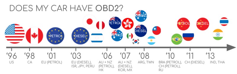
The good news is, if you own a relatively recent non-electric car, it almost certainly has an OBD II connector. While most modern cars with OBD II also utilize the CAN bus communication protocol, it’s important to note that the presence of a 16-pin connector doesn’t automatically guarantee OBD II compliance, especially in older vehicles. To confirm OBD II compliance, consider the vehicle’s origin and year of purchase:
A Brief History of OBD II and the Connector Standard
The OBD system’s origins trace back to California, driven by the California Air Resources Board (CARB) requirements for emission control in new cars from 1991 onwards. The Society of Automotive Engineers (SAE) played a key role in standardizing OBD, culminating in the OBD II standard. This standardization included defining Diagnostic Trouble Codes and, crucially, the OBD II connector itself, as per the SAE J1962 standard. This ensured a common interface across different vehicle manufacturers.
The rollout of OBD II was a phased process:
- 1996: OBD II became mandatory in the USA for cars and light trucks.
- 2001: Required in the EU for gasoline cars.
- 2003: Required in the EU for diesel cars (EOBD).
- 2005: OBD II became mandatory in the US for medium-duty vehicles.
- 2008: US vehicles were mandated to use ISO 15765-4 (CAN) as the foundation for OBD II communication.
- 2010: OBD II was extended to heavy-duty vehicles in the US.
The Future of OBD II and the Evolving Role of the Connector
While OBD II remains relevant, its future is evolving. Originally designed for emission control, legislated OBD II is not mandated for electric vehicles. Notably, most modern EVs do not support standard OBD II requests, opting instead for OEM-specific UDS communication. This shift presents challenges for accessing data from EVs, often requiring reverse engineering efforts, as seen in case studies for brands like Tesla, Hyundai/Kia, Nissan, and VW/Skoda.
In response to the limitations of traditional OBD II, newer protocols like WWH-OBD (World Wide Harmonized OBD) and OBDonUDS (OBD on UDS) have emerged. These aim to modernize OBD communication by utilizing the UDS protocol.
The concept of OBD3 envisions integrating telematics into all vehicles, enabling remote emission checks. This could involve using a radio transponder to transmit VIN and DTCs wirelessly. While convenient and cost-saving, OBD3 raises privacy concerns.
Interestingly, while OBD II was intended for repair shop diagnostics, it’s now widely used by third parties for real-time data access via OBD II dongles and CAN loggers. However, some automotive industry voices are advocating for restricting this third-party access, suggesting “turning off” OBD II functionality during driving and centralizing data collection with manufacturers, citing security and data control reasons. This potential shift could significantly impact the market for OBD II-based third-party services.
Learn More About CAN Bus
Want to deepen your understanding of CAN bus technology, which is closely linked to the OBD II connector?
Our comprehensive ‘Ultimate CAN Guide’ provides 12 easy-to-understand introductions in a 160+ page PDF document.
Download now
OBD II Standards and the Connector Specification
OBD II operates as a higher-layer protocol, similar to a language, while CAN serves as the communication method, akin to a phone line. OBD II shares similarities with other CAN-based higher-layer protocols like J1939, CANopen, and NMEA 2000.
The OBD II standards encompass various aspects, including the OBD II connector specifications, lower-layer communication protocols, and OBD II parameter IDs (PIDs).
These standards are structured using a 7-layer OSI model. Notably, both SAE and ISO standards cover several layers, reflecting the US (SAE) and EU (ISO) standards for OBD. Many standards are technically very close, for instance, SAE J1979 corresponds to ISO 15031-5, and SAE J1962 aligns with ISO 15031-3.
The OBD II Connector [SAE J1962 / ISO 15031-3]: Pinout and Functionality
The 16-pin OBD II connector is the standardized physical interface for accessing vehicle data, as defined in SAE J1962 and ISO 15031-3. The illustration above shows a Type A OBD II pin connector, often called the Data Link Connector (DLC).
Key points regarding the OBD II connector:
- Location: Typically found near the steering wheel, but its exact placement can vary and might be hidden.
- Pin 16: Provides battery power, often active even when the ignition is off.
- Pinout variation: The OBD II connector pinout is protocol-dependent.
- CAN bus: The most prevalent lower-layer protocol is CAN bus, meaning pins 6 (CAN-H) and 14 (CAN-L) are usually connected for CAN communication.
OBD II Connector Types: A vs. B
In practice, you might encounter Type A and Type B OBD II connectors. Type A is standard in cars, while Type B is more common in medium and heavy-duty vehicles.
Both types share a similar OBD II connector pinout, but they differ in power supply output: Type A delivers 12V, and Type B provides 24V. Baud rates can also differ, with cars typically using 500K, while heavy-duty vehicles often use 250K (with increasing support for 500K).
Visually, a Type B OBD II connector has an interrupted groove in the middle, distinguishing it from Type A. A Type B OBD II adapter cable is generally compatible with both Type A and Type B sockets, but a Type A adapter will not fit into a Type B socket.
OBD II and CAN Bus [ISO 15765-4] Communication via the Connector
Since 2008, CAN bus has been the mandatory lower-layer protocol for OBD II in US vehicles, as per ISO 15765. ISO 15765-4, also known as Diagnostics over CAN (DoCAN), specifies how CAN is used for OBD II, focusing on the physical, data link, and network layers.
Key specifications for OBD II communication over CAN include:
- Bit-rate: Must be 250K or 500K.
- CAN IDs: Can be 11-bit or 29-bit.
- CAN IDs for OBD: Specific CAN IDs are designated for OBD requests and responses.
- Data length: Diagnostic CAN frames must have a data length of 8 bytes.
- Cable length: The OBD II adapter cable should not exceed 5 meters.
OBD II CAN Identifiers (11-bit, 29-bit) and the Connector
OBD II communication via the OBD II connector always involves request/response message exchanges.
In most cars, 11-bit CAN IDs are used for OBD II. Functional addressing utilizes CAN ID 0x7DF, broadcasting requests to all OBD II-compatible ECUs. Physical addressing, using CAN IDs 0x7E0-0x7E7 for specific ECU requests, is less common.
ECUs respond with 11-bit IDs ranging from 0x7E8-0x7EF, with 0x7E8 (ECM – Engine Control Module) and 0x7E9 (TCM – Transmission Control Module) being the most frequent response IDs.
Some vehicles, especially vans and medium/heavy-duty vehicles, might employ extended 29-bit CAN identifiers for OBD II communication through the OBD II connector. Here, the functional addressing CAN ID is 0x18DB33F1. Responses use CAN IDs from 0x18DAF100 to 0x18DAF1FF, commonly 0x18DAF110 and 0x18DAF11E. These response IDs are sometimes represented in J1939 PGN format, specifically PGN 0xDA00 (55808), reserved for ISO 15765-2 in the J1939-71 standard.
OBD II vs. Proprietary CAN Protocols and the Connector Interface
It’s crucial to understand that vehicle ECUs primarily operate using OEM-specific proprietary CAN protocols, not OBD II, for their core functions. These OEM protocols are often unique to vehicle brands, models, and years. Interpreting this proprietary CAN data without OEM documentation or reverse engineering is generally not possible.
When you connect a CAN bus data logger to the OBD II connector, you might observe OEM-specific CAN data alongside OBD II data, typically broadcast at high rates. However, modern vehicles often incorporate a ‘gateway’ that restricts access to this OEM CAN data via the OBD II connector, allowing only OBD II communication.
Think of OBD II as an additional, higher-layer protocol that operates in parallel with the vehicle’s primary OEM-specific protocol. The OBD II connector provides a standardized access point to this additional diagnostic layer.
Bit-rate and ID Validation for Connector Communication
OBD II can utilize two bit-rates (250K, 500K) and two CAN ID lengths (11-bit, 29-bit), resulting in four possible combinations. Modern cars commonly use 500K and 11-bit IDs. Diagnostic tools should systematically validate these parameters.
ISO 15765-4 outlines a procedure for determining the correct combination, relying on the mandatory OBD II response to a specific request and detecting CAN error frames caused by incorrect bit-rate transmission.
Newer ISO 15765-4 versions acknowledge OBD communication via OBDonUDS alongside OBDonEDS. This article primarily focuses on OBD2/OBDonEDS (OBD on Emission Diagnostic Service), prevalent in most non-EV cars, versus WWH-OBD/OBDonUDS (OBD on Unified Diagnostic Service), mainly used in EU trucks/buses.
To differentiate between OBDonEDS and OBDonUDS protocols when using the OBD II connector, diagnostic tools can send UDS requests with 11-bit/29-bit functional address IDs for service 0x22 and data identifier (DID) 0xF810 (protocol identification). Vehicles supporting OBDonUDS ECUs should respond to this DID.
Five Lower-Layer OBD II Protocols Beyond CAN for the Connector
While CAN (ISO 15765) is now dominant for OBD II, older vehicles (pre-2008) might use one of four other lower-layer protocols accessible through the OBD II connector. The connector pinout can help identify the protocol in use.
- ISO 15765 (CAN bus): Mandatory in US cars since 2008 and widely used today.
- ISO14230-4 (KWP2000): Keyword Protocol 2000, common in 2003+ Asian cars.
- ISO 9141-2: Used in EU, Chrysler & Asian cars (2000-04).
- SAE J1850 (VPW): Primarily in older GM vehicles.
- SAE J1850 (PWM): Primarily in older Ford vehicles.
ISO-TP [ISO 15765-2] for OBD II Message Transport via the Connector
All OBD II data transmitted through the OBD II connector utilizes the ISO-TP transport protocol (ISO 15765-2) over CAN. This protocol enables transmission of data payloads exceeding the 8-byte CAN frame limit, essential for OBD II functions like retrieving VIN or DTCs. ISO 15765-2 manages segmentation, flow control, and reassembly of these larger messages.
For smaller OBD II data transmissions that fit within a single CAN frame, ISO 15765-2 specifies the ‘Single Frame’ (SF) format. In SF, the first data byte (PCI field) indicates the payload length, leaving 7 bytes for OBD II communication.
Understanding the OBD II Diagnostic Message Structure via the Connector
To better grasp OBD II communication over CAN, consider a simplified ‘Single Frame’ OBD II CAN message exchanged via the OBD II connector. An OBD II message comprises an identifier, data length (PCI field), and data. The data segment is further structured into Mode, parameter ID (PID), and data bytes.
Example: OBD II Request/Response via the Connector
Consider a request/response example for ‘Vehicle Speed’. An external tool sends a request to the car via the OBD II connector with CAN ID 0x7DF and 2 payload bytes: Mode 0x01 and PID 0x0D. The car responds with CAN ID 0x7E8 and 3 payload bytes, including the vehicle speed value in the 4th byte, 0x32 (decimal 50). Using OBD II PID decoding rules for 0x0D, we find this corresponds to 50 km/h.
The 10 OBD II Services (Modes) Accessed via the Connector
OBD II defines 10 diagnostic services, also known as modes. Mode 0x01 provides real-time data, while others are used for DTCs, freeze frame data, and more. Vehicles aren’t required to support all 10 modes and may have OEM-specific modes beyond these. In OBD II messages, the mode is in the 2nd byte of the data payload. In requests, the mode is directly included (e.g., 0x01), while in responses, 0x40 is added to the mode value (e.g., resulting in 0x41).
OBD II Parameter IDs (PIDs) and the Connector
Within each OBD II mode are parameter IDs (PIDs). For example, mode 0x01 includes ~200 standardized PIDs for real-time data like speed, RPM, and fuel level. However, vehicles typically support only a subset of PIDs within a mode.
One PID stands out: mode 0x01 PID 0x00. If an emissions-related ECU supports any OBD II services, it must support mode 0x01 PID 0x00. Responding to PID 0x00, the ECU indicates support for PIDs 0x01-0x20. PID 0x00 thus serves as a fundamental OBD II compatibility test. PIDs 0x20, 0x40, …, 0xC0 are used to determine support for the remaining mode 0x01 PIDs.
Tip: OBD II PID Overview Tool
SAE J1979 and ISO 15031-5 appendices contain scaling information for standard OBD II PIDs, enabling conversion of raw data to physical values. Our OBD II PID overview tool assists in constructing OBD II request frames and dynamically decoding responses, making working with the OBD II connector easier.
OBD2 PID overview tool
Practical Guide: Logging and Decoding OBD II Data from the Connector
This section outlines a practical example of logging OBD II data using a CANedge CAN bus data logger connected via the OBD II connector. The CANedge allows custom CAN frame transmission for OBD II logging. Connecting the CANedge to your vehicle is straightforward with an OBD2-DB9 adapter cable.
Review responses to ‘Supported PIDs’ requests using asammdf software.
#1: Validating Bit-rate, IDs, and Supported PIDs via the Connector
ISO 15765-4 provides guidance on determining the bit-rate and IDs used by a specific vehicle’s OBD II connector. You can use CANedge for this validation:
- Test at 500K: Send a CAN frame at 500K and check for successful transmission (if unsuccessful, try 250K).
- Bit-rate selection: Use the validated bit-rate for further communication.
- ‘Supported PIDs’ requests: Send multiple ‘Supported PIDs’ requests and analyze the responses.
- ID type determination: Response IDs indicate 11-bit vs. 29-bit CAN IDs.
- PID support discovery: Response data reveals supported PIDs.
Pre-configured settings are available to streamline these tests. Most post-2008 non-EV cars typically support 40-80 PIDs via 500K bit-rate, 11-bit CAN IDs, and the OBD2/OBDonEDS protocol when accessed through the OBD II connector.
As shown in the asammdf GUI screenshot, multiple responses to a single OBD request (using 0x7DF) are common due to polling all ECUs. Because all OBD2/OBDonEDS-compliant ECUs must support service 0x01 PID 0x00, many responses are common for this PID. Subsequent ‘Supported PIDs’ requests will receive fewer responses. The ECM ECU (0x7E8) often supports all PIDs supported by other ECUs, so reducing bus load is possible by directing requests specifically to the ECM using ‘Physical Addressing’ CAN ID 0x7E0 for subsequent communication via the OBD II connector.
#2: Configuring OBD II PID Requests for Connector Data
After identifying supported PIDs, bit-rate, and CAN IDs, configure your transmit list with desired PIDs for data logging via the OBD II connector.
Consider these factors for efficient logging:
- CAN IDs: Use ‘Physical Addressing’ request IDs (e.g., 0x7E0) to minimize redundant responses.
- Spacing: Introduce a 300-500 ms delay between OBD II requests to prevent ECU overload.
- Battery management: Implement triggers to stop transmissions when the vehicle is inactive to conserve battery.
- Filtering: Apply filters to record only OBD II responses if OEM-specific CAN data is also present.
With these configurations, your device is ready to log raw OBD II data from the OBD II connector.
Example CANedge OBD II PID request list for data logging through the OBD II connector.
Visualize DBC decoded OBD II data in asammdf software.
#3: DBC Decoding of Raw OBD II Data from the Connector
To analyze and visualize logged OBD II data, decode the raw data into physical values. Decoding information is in ISO 15031-5/SAE J1979 and online resources. Our free OBD II DBC file simplifies DBC decoding in CAN bus software tools.
Decoding OBD II data is more intricate than standard CAN signals because different OBD II PIDs share the same CAN ID (e.g., 0x7E8). The CAN ID alone isn’t enough to identify signals in the payload. Signal identification requires using the CAN ID, OBD II mode, and OBD II PID – a multiplexing method called ‘extended multiplexing,’ implementable in DBC files.
CANedge: Your OBD II Connector Data Logger
The CANedge enables easy OBD II data recording to 8-32 GB SD cards. Connect it to your vehicle’s OBD II connector to start logging and utilize free software/APIs and our OBD II DBC for data decoding.
OBD2 logger intro CANedge
OBD II Multi-Frame Examples [ISO-TP] via the Connector
While many examples are single-frame, OBD II also uses multi-frame communication via ISO-TP. Multi-frame communication requires flow control frames. CANedge configuration can use static flow control frames, e.g., 50 ms after the initial request. Analyzing multi-frame OBD II responses requires CAN software/API tools with ISO-TP support, like CANedge MF4 decoders.
Example 1: OBD II Vehicle Identification Number (VIN) Retrieval via the Connector
Retrieving the VIN via OBD II mode 0x09 and PID 0x02 accessed through the OBD II connector often involves multi-frame communication.
The tester tool sends a Single Frame request. The vehicle responds with a First Frame indicating a multi-frame response, followed by subsequent Consecutive Frames containing the VIN data. The VIN data is encoded in HEX and can be converted to ASCII.
Example 2: OBD II Multi-PID Request (6x) via the Connector
OBD II allows requesting up to 6 mode 0x01 PIDs in a single request frame via the OBD II connector. The ECU responds with data for supported PIDs, possibly across multiple frames. While efficient, this method complicates signal decoding and is generally not recommended for practical logging due to DBC file limitations and complex signal encoding specific to the request method.
Decoding multi-PID responses via DBC files is complex due to extended multiplexing and payload position variations, making generic DBC files unsuitable. Custom scripts and recording request messages can aid in interpretation, but these are challenging to scale.
Example 3: OBD II Diagnostic Trouble Codes (DTCs) Retrieval via the Connector
OBD II mode 0x03, accessed via the OBD II connector, retrieves emissions-related DTCs. No PID is needed in the request. ECUs respond with the number of stored DTCs and their 2-byte codes. Multi-frame responses are necessary if more than 2 DTCs are stored. DTC values are 2-byte codes, categorized and numerically coded according to ISO 15031-5/ISO 15031-6. Decoded DTCs can be looked up using OBD II DTC lookup tools.
Use Cases for OBD II Data Logging via the Connector
OBD II data, accessed through the OBD II connector, offers valuable insights for various applications in cars and light trucks:
Car Data Logging via the Connector
OBD II data logging can contribute to fuel efficiency, improved driving habits, prototype testing, and insurance telematics.
obd2 logger
Real-Time Car Diagnostics via the Connector
OBD II interfaces facilitate real-time streaming of human-readable diagnostic data for vehicle issue diagnosis.
obd2 streaming
Predictive Maintenance via the Connector
IoT-connected OBD II loggers enable remote vehicle monitoring for predictive maintenance, preventing breakdowns.
predictive maintenance
Vehicle Black Box Logging via the Connector
OBD II loggers can function as vehicle ‘black boxes’, providing crucial data for disputes or in-depth diagnostics.
can bus blackbox
Do you have an OBD II data logging application? Contact us for expert advice!
Contact us
Explore our guides section for more introductions, or download the comprehensive ‘Ultimate Guide’ PDF.
Ready to log or stream OBD II data?
Get your OBD II data logger today!
Buy now Contact us
Further Reading
OBD2 DATA LOGGER: EASILY LOG & CONVERT OBD2 DATA
CANEDGE2 – PRO CAN IoT LOGGER
[