As vehicles age, encountering issues with the oxygen sensor or air/fuel ratio sensor’s heater circuit becomes increasingly common. While the immediate solution might seem to be replacing the sensor, recurring heater circuit codes after sensor replacement indicate a deeper problem. This article, aimed at automotive technicians and DIY enthusiasts, delves into effective diagnostic techniques for Sensor Heater circuit faults, ensuring accurate repairs and preventing frustrating comebacks.
Often, the symptom presents as a check engine light accompanied by a trouble code related to the sensor heater circuit. A prevalent example is the P0031 code, signaling “O2 Sensor Bank 1 Sensor 1 Heater Circuit Low Current (Open Circuit).” In such cases, simply swapping out the sensor often proves ineffective, highlighting the need for a systematic diagnostic approach to pinpoint the root cause of the fault.
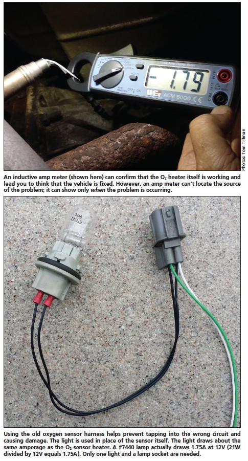
While both oxygen sensors and air/fuel ratio sensors serve distinct purposes in emissions control, their heater elements operate on the same fundamental principle. For diagnostic purposes concerning heater circuit failures, we can consider them collectively as “O2 sensors.” A common initial test involves checking the amperage of the sensor heater circuit. A successful amperage reading might misleadingly suggest a functional heater, yet the problem could lie in the timing or control of the heater circuit operation.
Consider this: is it necessary for the O2 sensor heater to be active when the engine is off? Likely not. The Engine Control Module (ECM) governs the heater circuit’s operation, and relying solely on an ammeter reading might only capture a snapshot of the circuit’s status without revealing intermittent or control-related issues.
For efficient electrical diagnostics, a straightforward testing method is invaluable. Using a #7440 incandescent light bulb and socket as a test tool for O2 sensor heater circuits proves remarkably effective. By connecting this light bulb assembly to the vehicle’s O2 sensor heater harness in place of the sensor, we introduce a known load (approximately 1.75A at 12V), typically within the sensor heater’s operating range. This method proves successful in approximately 95% of diagnostic scenarios.
Image: Promotional banner for aftermarket automotive parts and tools, indirectly relevant to sensor repair context.
When replacing a faulty O2 sensor, repurpose the old sensor’s harness by cutting off the sensor itself. Utilizing the original harness minimizes the risk of inadvertently tapping into the wrong circuit, a potentially costly error. Attach female spade connectors to each heater wire of the harness – these wires are usually black or white. Subsequently, connect the #7440 bulb and socket to this prepared harness.
Four-wire plug configurations are prevalent in aftermarket applications. However, O2 sensors with five or more wires also exist, all retaining two dedicated heater wires. Ensure you correctly match the plug and wiring configuration to the vehicle’s O2 sensor connector before proceeding with testing.
Begin by recording existing diagnostic trouble codes (DTCs), including freeze frame data, which captures the operating conditions when the code was set. Clear the codes afterward, as some vehicle systems deactivate the O2 heater circuit until codes are cleared.
With the ignition switch turned off, connect the test harness (with the light bulb) to the vehicle’s O2 sensor harness connection. The light should remain off. Upon starting the engine, the light should illuminate steadily or blink, indicating normal circuit operation. For safety, limit this test duration to 30 seconds to prevent potential code resets by the computer.
If the test light illuminates with the ignition off or in the “key on, engine off” position, a heater circuit malfunction is present. Consult the vehicle’s wiring schematic to understand the circuit’s wiring configuration.
O2 sensor heater circuits are typically controlled in one of two ways: positive control or negative control.
Positively Controlled Heater Circuit: In this configuration, the sensor heater’s negative wire is directly grounded. If the test light illuminates with the ignition off, suspect a short-to-power issue. Often, a relay controls the heater circuit in these systems. Remove the relay and retest. If the light persists, a short to voltage exists within the wiring harness upstream of the relay. Trace the harness from the O2 sensor connection back towards the relay. As you approach the short, the light might flicker or extinguish. In some instances, removing the relay will immediately turn off the light, indicating a shorted relay or a problem in the relay control circuit itself.
Negatively Controlled Heater Circuit: If the wiring diagram indicates ground control via the ECM, investigate a short-to-ground on the sensor’s negative control wire. A quick check involves disconnecting the ECM from the circuit (ensure ignition and battery are off before disconnecting, then reconnect battery and turn ignition on). If the short to ground is between the O2 heater connector and the ECM, the test light will remain on. Trace the wiring harness back to the computer while monitoring the light; the light may flicker or turn off as you near the short.
Consider a real-world scenario: a 2000 Jeep Grand Cherokee with a 4.0L engine exhibiting a P0031 code. Diagnosis revealed the O2 sensor harness pinched under the valve cover at the rear cylinder head. Crucially, only the sensor’s negative heater wire was affected due to a recent valve cover gasket replacement.
An insightful question arose from a technician: why did a short-to-ground on the control wire trigger an “open heater circuit” code? The ECM monitors for 12V on the sensor’s negative control wire when its internal heater circuit driver (power transistor) is inactive (open). When the control wire is grounded, the heater circuit activates immediately upon ignition, bypassing ECM control. Consequently, the ECM detects zero voltage while its driver is still open, interpreting this as an open heater circuit condition. This situation underscores how an ammeter reading alone can be misleading, suggesting a functioning circuit when a control fault exists.
Conversely, if the test light remains off with the engine running, initially check for a blown fuse. A shorted O2 sensor heater can cause fuse failure.
If the fuse is intact, verify voltage at the O2 sensor harness connection using the modified test harness. Remember, the engine must be running for this test. Near-zero voltage on the positive heater wire indicates an open circuit in the power wire leading back to the fuse, possibly involving a relay. However, if battery voltage is present on both heater wires at the O2 sensor harness (with the test light still connected and off), suspect an open circuit in the sensor’s negative wire or a computer grounding issue, potentially a dedicated ground for this circuit. The most severe scenario at this stage is a failed ECM driver.
While the light bulb test is highly effective (approximately 95% success rate), exceptions exist. A 1997 Toyota 4Runner with a V6 engine presented such a case. Voltage was present on both heater wires, but the system also monitored current flow. The test light’s current draw was outside the Toyota system’s acceptable range, causing the ECM to shut down the circuit to protect its components.
In such situations, connect a new sensor directly to the harness for testing, without installing it in the exhaust. This eliminates the sensor itself as the fault. Monitor the voltage on the sensor’s negative heater wire. Upon engine start, 12V should appear momentarily, then drop to zero or pulse. A lab scope best visualizes this pulsing, showing increased “on-time” as the heater cycles. A digital voltmeter (DVOM) can be used, but its averaged reading might be less conclusive.
In conclusion, whenever replacing an oxygen sensor due to a heater circuit code, always validate the circuit operation. The simple light bulb test provides a rapid and effective method for circuit verification, minimizing comebacks and saving valuable diagnostic time. Thoroughly diagnosing sensor heater circuits using these techniques ensures accurate repairs and enhances customer satisfaction.