For auto repair professionals, wiring diagrams are indispensable tools. They are the roadmaps to a vehicle’s complex electrical system, guiding you through circuits to diagnose issues accurately and efficiently. Understanding the symbols within these diagrams is not just helpful—it’s essential for effective troubleshooting and repair. This guide dives deep into the world of Symbols In Wiring Diagrams, ensuring you can confidently navigate and interpret these critical schematics.
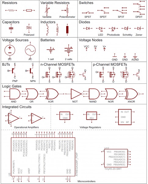
Overview of common schematic symbols used in electronic diagrams.
Essential Symbols in Automotive Wiring Diagrams
Let’s break down the core symbols you’ll encounter in automotive wiring diagrams. Mastering these symbols is the first step to becoming proficient in reading and utilizing these schematics for car repairs.
Power Supply Symbols
Power is the lifeblood of any electrical system, and wiring diagrams clearly indicate its sources and distribution.
Battery
The battery symbol in a wiring diagram is crucial as it represents the main power source of the vehicle. It’s typically depicted as a series of unequal parallel lines. Usually, two sets of lines are used, and sometimes more pairs indicate multiple cells within a battery system, although in automotive diagrams, it primarily symbolizes the 12V or 24V vehicle battery. The longer line represents the positive terminal, and the shorter line indicates the negative terminal (ground).
Common symbols representing batteries in electrical schematics, illustrating both standard and multi-cell battery representations.
Ground
Ground symbols are just as vital as battery symbols. They indicate the electrical ground or chassis ground, serving as the return path for current in the circuit. Multiple ground symbols exist, but they all represent the same concept: a zero-voltage reference point. Common ground symbols include three parallel lines decreasing in size, a triangle pointing downwards, or sometimes a simple single line. In automotive contexts, you’ll frequently see the chassis ground symbol, indicating the connection to the vehicle’s metal frame.
Various symbols used to denote electrical ground in circuit diagrams, including chassis ground and earth ground.
Voltage Nodes (Power Rails)
For simplifying complex diagrams, voltage nodes represent direct connections to specific voltage levels. Symbols like arrows pointing upwards often denote positive voltage supplies (e.g., 12V, 5V), while ground symbols also function as voltage nodes for 0V. These are single-terminal symbols, making it easier to connect multiple components to the same power supply without drawing extensive wire lines across the schematic. Common voltage nodes in automotive diagrams include B+ (Battery positive), VCC (common collector voltage, often for ECU power), and GND (Ground).
Protection Devices
Safety and circuit integrity are paramount, and wiring diagrams clearly mark protection devices.
Fuses
Fuses are critical safety components designed to protect circuits from overcurrent conditions. The fuse symbol typically looks like a zig-zag line enclosed in a rectangle or just a simple rectangle with terminals extending outwards. When excessive current flows through a fuse, the internal filament melts, breaking the circuit and preventing damage to other components. Automotive wiring diagrams will show fuses in various circuits, protecting everything from headlights to critical engine control systems.
Schematic symbols for fuses and PTC thermistors, components used for circuit protection against overcurrent.
Circuit Breakers
Similar to fuses, circuit breakers protect circuits from overcurrent, but they can be reset and reused. Their symbol often resembles a switch combined with a fuse. A common symbol is a small rectangle with a curved line or a switch-like actuator incorporated. In automotive applications, circuit breakers are used for high-current circuits like power windows or door locks, where temporary overloads might occur.
Switches and Relays
Controlling the flow of current is managed by switches and relays, each with distinct symbols.
Switches
Switches allow circuits to be opened or closed, controlling the flow of electricity. The simplest switch, Single Pole Single Throw (SPST), is represented by two terminals with a line representing the switch actuator. More complex switches like Single Pole Double Throw (SPDT) or Double Pole Double Throw (DPDT) have symbols that extend from the basic SPST, indicating multiple poles and throws. In automotive diagrams, you’ll see switches for lights, ignition, and various accessories.
Illustrations of SPST, SPDT, and DPDT switch symbols, demonstrating different switch configurations in electrical schematics.
Relays
Relays are electromechanical switches used to control a high-current circuit with a low-current signal. The relay symbol consists of a coil symbol (often a looped or curved line) and a switch symbol. When current flows through the coil, it creates a magnetic field that operates the switch. Relays are extensively used in vehicles for controlling headlights, starter motors, and other high-power devices. Wiring diagrams will clearly distinguish between the relay coil circuit and the switched circuit.
A schematic symbol for a relay, highlighting the coil that actuates the switch contacts.
Connectors and Terminals
Connections are where components interface, and their symbols are crucial for tracing circuits across different parts of a vehicle.
Connectors
Connectors are used to join wires and components together, allowing for modularity and easier assembly/disassembly. Connector symbols can vary but often look like interlocking shapes or a series of squares or circles. They are usually labeled with pin numbers or letters to match physical connectors. Automotive wiring diagrams are filled with connector symbols, representing everything from simple inline connectors to complex multi-pin ECU connectors.
Examples of schematic symbols for electrical connectors, representing different types of connections.
Terminals
Terminals represent points of connection, often where wires attach to components. They might be shown as small circles or dots where wires meet symbols. Understanding terminal markings on diagrams is crucial for correctly identifying connection points in the actual vehicle wiring.
Wires and Conductors
Wires are the pathways of electricity, and diagrams represent them simply but effectively.
Conductors (Wires)
Wires are shown as lines connecting components. In color wiring diagrams (increasingly common), different line colors represent wires of different colors in the vehicle. Line thickness might sometimes indicate wire gauge or current carrying capacity, but color is the primary differentiator. Following these lines is how you trace a circuit’s path.
Passive Components: Resistors, Capacitors, and Inductors
These fundamental components shape circuit behavior, and their symbols are essential to recognize.
Resistors
Resistors limit current flow in a circuit. The resistor symbol is typically a zig-zag line or a rectangle (international standard). Variable resistors or potentiometers, which allow for adjustable resistance, add an arrow through the standard resistor symbol. In automotive systems, resistors are used in sensor circuits, voltage dividers, and to limit current to LEDs and other components.
Different schematic symbols for resistors, showing both the zig-zag and rectangular (international) representations, as well as symbols for potentiometers and variable resistors.
Capacitors
Capacitors store electrical energy. The capacitor symbol consists of two parallel lines, either both straight or one straight and one curved. The curved line indicates a polarized capacitor (usually electrolytic), where polarity must be observed in the circuit. Non-polarized capacitors have two straight lines. Capacitors are used for filtering, smoothing voltage, and timing circuits in automotive electronics.
Symbols for polarized and non-polarized capacitors in electrical schematics, differentiating between electrolytic and ceramic capacitor representations.
Inductors (Coils)
Inductors, or coils, store energy in a magnetic field and resist changes in current. The inductor symbol is usually a series of loops or curved humps. In vehicles, inductors are found in relays, solenoids, and ignition coils.
Schematic symbols for inductors, also known as coils, used in electronic circuits.
Actuators and Output Devices
These components convert electrical energy into mechanical motion or other actions.
Motors
Motors convert electrical energy into mechanical motion. The motor symbol is typically a circle with an “M” inside. More detailed symbols might include brushes or field coils, but the encircled “M” is most common. Automotive diagrams will show motors for window lifts, wipers, fans, fuel pumps, and more.
Schematic symbols for electric motors, commonly used in automotive applications.
Solenoids
Solenoids are electromechanical devices that use an electromagnetic coil to create linear motion. The symbol often looks like an inductor symbol connected to a mechanical actuator representation. In cars, solenoids control valves, actuators in transmissions, and starter mechanisms.
Speakers and Buzzers
Speakers and buzzers convert electrical signals into audible sound. The speaker symbol resembles a loudspeaker, while a buzzer might be similar but sometimes with slight variations to differentiate them. These are found in warning systems, audio systems, and chimes within vehicles.
A schematic symbol for a speaker, representing audio output devices in circuits.
Semiconductors: Diodes and Transistors
Semiconductors are the building blocks of modern electronics, controlling and amplifying electronic signals.
Diodes
Diodes allow current to flow in one direction only. The diode symbol is a triangle pointing to a line. Light Emitting Diodes (LEDs) are indicated by the standard diode symbol with two arrows pointing away, representing light emission. Zener diodes and Schottky diodes have variations on the standard diode symbol to denote their specific characteristics. In automotive applications, diodes are used for rectification, voltage regulation (Zener), and LEDs for lighting and indicators.
Schematic symbols for diodes, including standard diodes, LEDs (Light Emitting Diodes), and photodiodes.
Transistors
Transistors are semiconductor devices used to amplify or switch electronic signals and power. Bipolar Junction Transistors (BJTs) and Metal-Oxide-Semiconductor Field-Effect Transistors (MOSFETs) are common types, each with their own set of symbols, differentiating between NPN/PNP and N-channel/P-channel configurations. Transistors are fundamental in ECU circuitry, sensor interfaces, and various control modules in vehicles.
A variety of MOSFET and BJT (Bipolar Junction Transistor) symbols used in circuit diagrams, showing different transistor types and configurations.
Integrated Circuits (ICs) and Modules
Complex functionalities are often encapsulated in integrated circuits or modules, represented by simplified symbols.
Integrated Circuits (ICs)
Integrated Circuits (ICs) are complex circuits miniaturized into a single package. Their symbol is typically a rectangle with pins labeled with numbers and functions. In automotive diagrams, ICs represent ECUs, sensors, driver chips, and more. Due to their complexity, the symbol is generic, and identification relies heavily on part numbers and labels.
Examples of schematic symbols for Integrated Circuits (ICs), highlighting the generic rectangular shape with pin designations.
Modules (ECUs, Control Units)
Larger modules like Engine Control Units (ECUs), Transmission Control Modules (TCUs), or Body Control Modules (BCMs) might be represented as rectangles with labeled connectors. These symbols represent entire subsystems within the vehicle.
Understanding Wiring Diagram Structure
Beyond individual symbols, understanding how they are connected in a wiring diagram is crucial.
Nets, Nodes, and Junctions
Nets are the connections between components, shown as lines. Nodes or junctions, represented by dots at wire intersections, indicate connected wires. If wires cross without a dot, they are not electrically connected. Net names or labels are used to simplify diagrams, indicating that nets with the same name are connected, even if not visually linked by a line.
Illustrations of connected and disconnected wire junctions in schematics, emphasizing the role of nodes in indicating electrical connections.
Wire and Component Labels
Labels are critical for identifying components and wires. Component names (e.g., R1 for Resistor 1, C2 for Capacitor 2) and values (e.g., 100Ω, 10µF) are placed near their symbols. Wire labels might indicate circuit function, wire gauge, or color code. Understanding these labels is key to correctly interpreting the diagram.
Circuit Paths and Flow
Wiring diagrams are designed to show the flow of current from the power source to ground, through various components. Tracing these paths is fundamental to understanding circuit operation and diagnosing faults.
Block Diagrams within Wiring Diagrams
Complex wiring diagrams may include block diagrams, simplifying sections into functional blocks (e.g., “Engine Control System,” “ABS Module”). These help to understand the overall system architecture before diving into detailed circuit tracing.
Tips for Reading Automotive Wiring Diagrams
Here are practical tips to enhance your wiring diagram reading skills:
- Start with the Power Source and Ground: Identify the battery and ground symbols to understand the power supply framework of the system.
- Trace Circuits Step-by-Step: Follow the lines (nets) from the power source through components to ground to understand the path of current flow for each circuit.
- Use Component and Connector Identification: Utilize component names, values, and connector labels to precisely identify parts on the diagram and in the vehicle.
- Refer to Vehicle-Specific Wiring Diagrams: Always use the wiring diagram specific to the vehicle make, model, and year for accuracy. Generic diagrams are helpful for learning symbols but not for specific repairs.
- Practice and Familiarity: The more you practice reading wiring diagrams, the more comfortable and proficient you will become. Start with simpler circuits and gradually move to more complex schematics.
Conclusion
Mastering the symbols in wiring diagrams is a cornerstone skill for any auto repair professional. It empowers you to diagnose electrical issues accurately, perform repairs efficiently, and understand the intricate electrical systems of modern vehicles. By understanding these symbols and practicing diagram reading, you’ll significantly enhance your diagnostic capabilities and become a more effective and knowledgeable technician. Continue to explore vehicle-specific diagrams and resources to deepen your expertise and keep pace with the evolving technology in automotive electrical systems.