As automotive repair professionals at keyfobprog.com, we understand the increasing complexity of modern vehicles. Diagnosing issues isn’t just about listening to the engine anymore; it’s about understanding the intricate dance of electronic signals within your car’s systems. One crucial tool in this diagnostic arsenal is the Timing Graph. While often associated with software design in UML, the principle of a timing graph is incredibly relevant and powerful for automotive diagnostics, helping us visualize and interpret signals over time.
Timing Graphs: Visualizing the Rhythm of Your Engine
Think of a timing graph as a visual representation of events happening in your car’s electrical system over a period of time. Instead of just seeing static values, a timing graph allows us to see how those values change and when they change in relation to each other. This dynamic view is invaluable when diagnosing intermittent problems, sensor issues, or timing-related malfunctions within the engine and other vehicle systems.
Just like UML timing diagrams track conditions across lifelines over a linear time axis, automotive timing graphs track signal behavior across different components in your car. These graphs are essential for understanding the sequence and timing of events, especially when troubleshooting sophisticated systems.
Understanding the Basics of Automotive Timing Graphs
Let’s break down the core concepts of timing graphs as they apply to automotive diagnostics:
Signal Timeline Representation
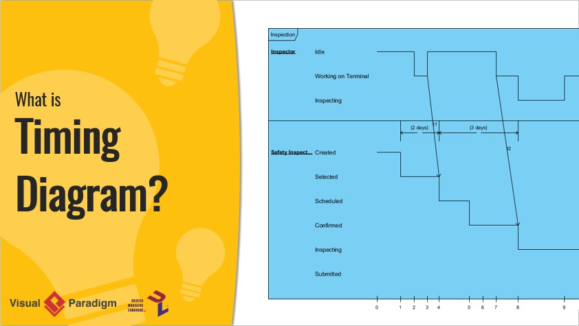
In a timing graph, changes in a signal’s state, such as voltage level (high/low, on/off), are shown as changes in the level of a lifeline. Imagine a horizontal line representing time. As the signal’s state changes, the line vertically shifts to a new level. A consistent state is represented by a horizontal segment of the line. A vertical jump indicates a change in the signal’s state.
For example, consider a crankshaft position sensor. Its signal might switch between high and low voltage as the crankshaft rotates. A timing graph would visually display these transitions, allowing you to quickly see if the signal is clean, consistent, and occurring at the expected intervals.
Value Timeline Representation
Another way to represent timing data is through a value lifeline. Instead of distinct states, this representation shows the continuous value of a signal over time. This is particularly useful for analog sensors, like temperature or pressure sensors, where the output is a varying voltage level rather than a simple on/off signal.
In a value lifeline, the signal’s value is plotted between two horizontal lines. The lines cross each other each time the value changes direction, creating a visual waveform that directly reflects the signal’s fluctuations over time.
Key Components of Automotive Timing Graphs
To effectively use timing graphs in automotive diagnostics, it’s crucial to understand their key components:
Lifeline: Representing Electrical Signals
In the context of automotive timing graphs, a lifeline represents a specific electrical signal you are measuring. This could be the signal from:
- Crankshaft Position Sensor (CKP): Essential for engine timing and ignition.
- Camshaft Position Sensor (CMP): Works with the CKP to determine piston position and valve timing.
- Oxygen Sensor (O2 Sensor): Monitors exhaust gas composition for fuel mixture control.
- Throttle Position Sensor (TPS): Indicates throttle valve angle to the engine control unit (ECU).
- Wheel Speed Sensor (WSS): Used by ABS and traction control systems.
You can display multiple lifelines on the same graph to compare signals from different sensors simultaneously, which is crucial for diagnosing interactions and dependencies between systems.
State Timeline: Analyzing Signal Conditions
A state timeline is used to visualize the different states or conditions of a signal over time. For digital signals, these states might be simply “High” and “Low”. For more complex signals, you might define states based on voltage ranges or signal characteristics.
Analyzing the sequence and duration of these states helps identify anomalies. For example, a missing pulse in a CKP sensor signal state timeline would immediately indicate a potential sensor malfunction or timing issue.
Multiple Lifelines: Inter-Signal Relationships
Just as UML timing diagrams can stack lifelines to show interactions, automotive timing graphs can display multiple lifelines. This allows you to visualize the relationship between different signals. For instance, you can compare the CKP and CMP signals to verify correct engine timing, or analyze the relationship between throttle position and airflow sensor signals to diagnose intake system issues.
State Lifeline: Focusing on State Changes
A state lifeline specifically highlights the changes in a signal’s state over time. The vertical axis lists the possible states, and the horizontal axis represents time. The lifeline traces the signal’s state transitions, making it easy to identify the sequence of events and the duration of each state.
Value Lifeline: Analyzing Signal Amplitude
A value lifeline, as discussed earlier, focuses on the continuous value of a signal. This is essential for analyzing analog signals where the amplitude or voltage level is critical. By observing the waveform in a value lifeline, you can detect signal degradation, noise, or incorrect signal levels.
Timeline and Constraints: Measuring Timing Accuracy
The timeline at the bottom of the timing graph provides a time scale, allowing you to measure the duration of events and the intervals between them. Constraints can be added to the timeline to mark specific time points or intervals of interest.
For example, you can measure the time between pulses from the CKP sensor to verify the engine’s RPM, or check if the fuel injector pulse width is within the expected range. Timing constraints help you quickly assess if signals are occurring within specified time windows, which is crucial for diagnosing timing-related problems.
State and Value Lifelines Combined
You can effectively combine state and value lifelines within the same timing graph to get a comprehensive view of signal behavior. This allows you to simultaneously analyze both the discrete states and the continuous value variations of different signals, providing a richer understanding of system dynamics.
Timing Graphs in Automotive Diagnostics: Real-World Application
Timing graphs are not just theoretical concepts; they are a practical tool used daily by automotive technicians. When you connect a diagnostic oscilloscope to your car, you are essentially capturing data to create timing graphs. These graphs help you:
- Verify Sensor Functionality: Check if sensors are producing signals with the correct frequency, amplitude, and waveform.
- Diagnose Timing Issues: Identify problems with engine timing, ignition timing, or valve timing by analyzing CKP and CMP signals.
- Troubleshoot Communication Networks: Analyze CAN bus or other communication signals to pinpoint network faults.
- Identify Intermittent Problems: Capture transient signal anomalies that might be missed with static diagnostic codes.
- Compare Signals: Analyze the relationship between multiple signals to diagnose complex system interactions.
Integrating Timing Graphs with Other Diagnostic Tools
Timing graphs are most powerful when used in conjunction with other diagnostic tools, such as:
- Scan Tools: Retrieve diagnostic trouble codes (DTCs) and live data parameters, which can guide your timing graph analysis.
- Wiring Diagrams: Understand the electrical circuits and sensor locations to probe the correct signals.
- Technical Service Bulletins (TSBs): Provide known issues and diagnostic procedures that may involve timing graph analysis.
Just as UML timing diagrams are consistent with sequence diagrams, automotive timing graphs complement other diagnostic data. For example, a DTC indicating a CKP sensor fault can be further investigated and confirmed by analyzing the CKP sensor signal on a timing graph.
Master Automotive Diagnostics with Timing Graphs
Understanding and utilizing timing graphs is a crucial skill for modern automotive technicians. By visualizing the dynamic behavior of electrical signals, you can gain deeper insights into your car’s systems and diagnose complex issues with greater accuracy and efficiency. Embrace timing graphs as a powerful tool in your diagnostic toolbox, and you’ll be able to “decode” your car’s signals like never before.
For further learning and advanced diagnostic techniques, explore resources on automotive oscilloscopes and signal analysis. Mastering timing graphs will elevate your diagnostic skills and keep you ahead in the rapidly evolving world of automotive technology.