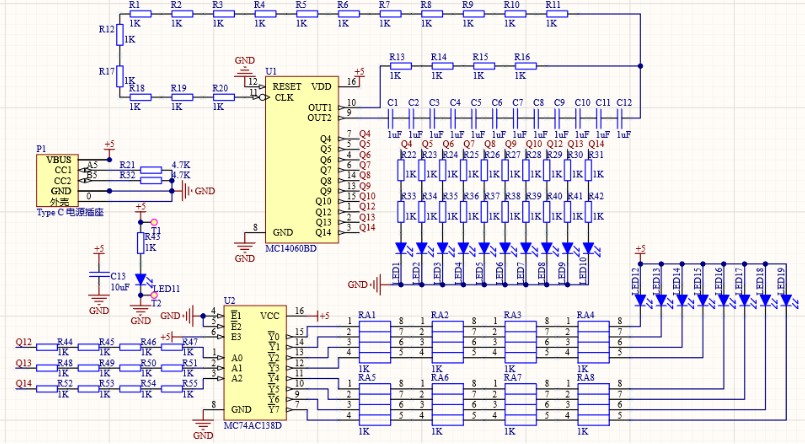
Schematic diagrams are the blueprints of electronic circuits, and understanding them is crucial for anyone working with electronics, from hobbyists to professional auto repair technicians. These diagrams use a systematic language of symbols, lines, letters, and numbers to represent components and their connections. For those just starting out, deciphering what these letters and numbers mean can seem daunting. This guide will break down the meaning behind these markings, helping you to read schematics more effectively and understand the intricate world of circuit design.
Component Designators: Identifying Types of Components
In a schematic, the letters preceding the numbers are known as component designators. These are standardized abbreviations that instantly tell you the type of electronic component you are looking at. This standardization is incredibly helpful, as it allows engineers and technicians worldwide to understand and work with schematics regardless of their origin. Let’s explore some of the most common component designators:
-
R – Resistor: (e.g., R1, R15, R100) – ‘R’ always indicates a resistor. Resistors are fundamental components that impede the flow of electrical current. The numbers following ‘R’ simply differentiate between multiple resistors within the same circuit. For instance, R1 might be a pull-up resistor, while R2 could be part of a voltage divider.
-
C – Capacitor: (e.g., C1, C5, C22) – ‘C’ denotes a capacitor. Capacitors store electrical energy in an electric field and are used for various purposes, including filtering signals, smoothing power supplies, and timing circuits. Like resistors, the numbers after ‘C’ distinguish individual capacitors in the schematic. C1 might be a decoupling capacitor, while C2 could be used in a timing circuit.
-
L – Inductor: (e.g., L1, L8, L12) – ‘L’ represents an inductor. Inductors store energy in a magnetic field and are often used in filters, power supplies, and radio frequency (RF) circuits. They can block changes in current. L1 might be a filter inductor, while L2 could be part of a resonant circuit.
-
D – Diode: (e.g., D1, D4, D17) – ‘D’ signifies a diode. Diodes are semiconductor devices that allow current to flow primarily in one direction. They are used for rectification, signal modulation, and protection. D1 could be a rectifier diode, while D2 might be a Zener diode for voltage regulation.
-
Q – Transistor: (e.g., Q1, Q3, Q9) – ‘Q’ is the designator for a transistor. Transistors are semiconductor devices used to amplify or switch electronic signals and power. They are the building blocks of modern electronics. Q1 might be a switching transistor, while Q2 could be used in an amplifier stage.
-
U – Integrated Circuit (IC): (e.g., U1, U6, U11) – ‘U’ indicates an integrated circuit (IC). ICs are complex circuits miniaturized and packaged into a single chip. They can range from simple operational amplifiers to complex microprocessors. U1 could be a microcontroller, while U2 might be an op-amp.
-
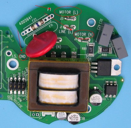
J – Connector: (e.g., J1, J2, J7) – ‘J’ represents a connector or jack. Connectors provide points where external circuits or components can be connected to the PCB. J1 might be a power input connector, while J2 could be an output connector for a sensor.
-
SW – Switch: (e.g., SW1, SW3, SW5) – ‘SW’ denotes a switch. Switches are used to open or close electrical circuits, controlling the flow of current. SW1 could be a power switch, while SW2 might be a user-controlled function switch.
-
TP – Test Point: (e.g., TP1, TP4, TP8) – ‘TP’ signifies a test point. Test points are specific locations in a circuit designed to allow for easy voltage or signal measurement during testing and troubleshooting. TP1 might be a test point for the main power rail, while TP2 could be for a specific signal line.
-
LED – Light Emitting Diode: (e.g., LED1, LED2, LED6) – ‘LED’ explicitly stands for a light-emitting diode. LEDs are semiconductor light sources that emit light when current flows through them. LED1 might be a power indicator LED, while LED2 could be used for status indication.
-
F – Fuse: (e.g., F1, F2, F5) – ‘F’ represents a fuse. Fuses are safety devices designed to protect circuits from overcurrent conditions by breaking the circuit if the current exceeds a safe level. F1 is typically the main fuse protecting the entire circuit.
-
VR or P – Variable Resistor/Potentiometer: (e.g., VR1, P1, VR5) – ‘VR’ or ‘P’ indicates a variable resistor or potentiometer. These are resistors whose resistance can be adjusted, often used for tuning circuits or user adjustments like volume control. VR1 might be used for calibration, while P1 could be a user-adjustable control.
-
M – Motor: (e.g., M1, M2, M3) – ‘M’ denotes a motor. Motors convert electrical energy into mechanical motion. M1 could be a DC motor, while M2 might be a stepper motor.
This is not an exhaustive list, but it covers the most common component designators you’ll encounter. Understanding these basic designations is the first step in reading any schematic diagram.
| Letter | Represents Components |
|---|---|
| D | Diode/Inverter |
| Q | Transistor |
| C | Capacitor |
| L | Inductor |
| R | Resistor |
| K | Relay |
| T | Transformer |
| X, Y | Crystal Oscillator |
| U, IC | Integrated Circuit |
| M | Motor |
| CX | High Voltage Ceramic Capacitor |
| CY | High Voltage Thin Film Capacitor |
| CE | Electrolytic Capacitor |
| VR | Variable Resistor |
| RT | Thermal Resistor |
| RP | Potentiometer |
| RG | GND (Ground Resistor – less common) |
| J | Joggle (Connector – likely typo, should be Connector/Jack) |
| JP | Jumper |
| FU | Fuse |
| N | Optocoupler |
| B, BZ | Buzzer |
| SCR | Unidirectional Thyristor |
| TRIAC | Bidirectional Thyristor |
| FB | Ferrite Bead |
| ZD | Zener Diode |
| LED | Light-Emitting Diode |
| SPK | Speaker |
| S, SW | Switch |
| DB | Bridge Diode |
| TP | Test Point |
Reference Numbers: Differentiating Components
The numbers that follow the component designators are reference numbers. These numbers are essential for distinguishing between multiple components of the same type within a single schematic. Without these numbers, it would be practically impossible to discuss, assemble, troubleshoot, or modify a circuit accurately.
For example, if you see R1, R2, and R3 on a schematic, you know these are three distinct resistors. Similarly, C1, C2, and C3 represent three different capacitors. These numbers provide a unique identifier for each component, eliminating any ambiguity.
Typically, reference numbers are assigned sequentially, starting from 1 for each component type and incrementing as more components of that type are added to the schematic. So, the first resistor you place might be R1, the second R2, and so on. This systematic numbering makes it easy to locate and refer to specific components.
Values and Ratings: Specifying Component Characteristics
Beyond identifying the type of component, schematics also use numbers to specify the electrical values and ratings of components. These values are critical for understanding how the circuit is designed to function and for selecting the correct parts for building or repairing the circuit.
-
Resistors: Resistor values are given in ohms (Ω). You might see notations like “R1 100Ω,” indicating that resistor R1 has a resistance of 100 ohms. Larger values can be expressed with prefixes like kilo (kΩ) for thousands of ohms and mega (MΩ) for millions of ohms. For example, “R5 10kΩ” is a 10,000-ohm resistor.
-
Capacitors: Capacitance is specified in farads (F), although in practice, you’ll more commonly see microfarads (µF), nanofarads (nF), or picofarads (pF) because farads are a very large unit. “C2 10µF” indicates a capacitor with a capacitance of 10 microfarads.
-
Inductors: Inductance is measured in henries (H), but similar to capacitors, you’ll often see millihenries (mH) or microhenries (µH). “L1 100mH” means an inductor with an inductance of 100 millihenries.
-
Voltage Ratings: Many components, particularly capacitors and semiconductors, have voltage ratings. This rating indicates the maximum voltage the component can safely handle without failing. A capacitor labeled “C4 25V” can withstand up to 25 volts. Exceeding this voltage can damage or destroy the component.
-
Tolerance and Power Ratings: For resistors especially, you may see tolerance ratings (e.g., ±5%), which indicate the precision of the resistor’s value compared to its stated value. Power ratings (in watts, W) specify the maximum power a resistor can dissipate without overheating. “R10 1kΩ ±1% 0.25W” is a 1 kilo-ohm resistor with 1% tolerance and a 0.25-watt power rating.
Pin Numbers and Labels: Understanding Connections
Components with multiple terminals, such as ICs, connectors, and transistors, use pin numbers and labels on schematics to clarify connections. Pin numbers are usually sequential numbers assigned to each terminal of the component.
For ICs and connectors, pin numbers are essential for correctly connecting the component into the circuit. Datasheets for these components will always reference pin numbers, and the schematic will mirror these numbers.
Furthermore, pin labels provide functional information about each pin. Common labels include:
- VCC or V+: Positive power supply voltage.
- GND: Ground or 0V reference.
- Output: Signal output pin.
- Input: Signal input pin.
- CLK: Clock signal input.
- RESET: Reset input.
For example, a slide potentiometer might have pins labeled “Output,” “VCC,” and “GND,” clearly indicating how to connect it to the circuit. Understanding these labels is vital for proper circuit construction and troubleshooting.
Nodes and Signal Labels: Tracing Circuit Paths
Nodes in a schematic are points where two or more components connect. These nodes are often implicitly understood at every junction of lines, but in complex schematics, they may be explicitly labeled with numbers or names for clarity.
Signal labels are text descriptions assigned to wires or traces in the schematic. These labels are crucial for understanding signal flow, especially in multi-page schematics or complex designs. Common signal labels include:
- GND: Indicates a connection to ground, the common reference point in the circuit.
- VCC (+5V, +12V, etc.): Power supply rails, indicating connections to specific voltage levels.
- CLK: Clock signals, used for timing and synchronization in digital circuits.
- DATA: Data lines, used for transmitting information in digital circuits.
- RESET: Reset signals for microcontrollers or other digital devices.
Signal labels are especially helpful for tracing connections across different parts of a large schematic. If a signal is labeled “DATA_IN” on one part of the schematic and the same label appears elsewhere, you know those points are electrically connected, even if they are not directly drawn as connected on the page.
Wire and Trace Identifications: Showing Connections
Wires and traces are represented as lines in a schematic, visually showing the electrical connections between components. In simpler schematics, these lines are typically unlabeled, and the connections are clear from the visual layout. However, in complex schematics, especially those spanning multiple pages, wires and traces may be labeled with names or numbers.
These labels can be simple sequential identifiers (e.g., A1, A2, A3) or more descriptive names that indicate the signal they carry (e.g., SCL, SDA for I2C communication, SPI_MOSI for SPI communication). Labeling wires and traces is vital for managing complexity and ensuring clarity in larger schematics.
Voltage and Current Values: Indicating Circuit Performance
Some schematics go beyond just component values and include voltage and current values directly on the diagram. These annotations provide insights into the expected circuit performance at various points.
- Voltage values might be placed near power supply lines or test points, indicating the expected voltage at that location (e.g., “5V,” “12V”).
- Current values are less commonly shown directly on the schematic but may appear in specific areas, especially for components like LEDs, indicating the intended current flow (e.g., “20mA”).
These values are often design targets or simulated values and are helpful for understanding the intended operation of the circuit and for troubleshooting if measured values deviate significantly.
Special Symbols: Representing Specific Features
Finally, schematics use special symbols to represent certain circuit features or concepts:
- Ground (GND) Symbol: A distinct symbol (often resembling an inverted triangle or a series of decreasing horizontal lines) represents the ground connection, the common zero-voltage reference in the circuit.
- Power Rail Symbols: Symbols like a filled triangle or an arrow can indicate power supply connections, often labeled with the voltage value (e.g., “+5V,” “+12V”).
- Oscillator/Clock Symbols: Symbols representing waveforms or the abbreviation “CLK” are used to denote oscillators or clock signal sources.
It’s important to remember that while there are common conventions, the exact meaning of letters and numbers on a schematic can sometimes vary slightly depending on the designer or company standards. If you encounter unfamiliar labels or symbols, especially in proprietary schematics, it’s always best to consult the associated documentation or clarify with the schematic’s creator. However, the principles outlined in this guide provide a solid foundation for understanding the vast majority of electronic schematic diagrams you will encounter. Understanding these fundamental elements empowers you to effectively read and interpret schematics, whether you are diagnosing an automotive electrical issue or designing your own electronic project.