As an automotive technician, wire diagrams are your roadmap to diagnosing and fixing electrical issues in vehicles. Understanding the symbols used in these diagrams is not just helpful—it’s essential. This guide will transform you into a proficient reader of automotive wire diagrams by explaining the most common Wire Diagram Symbols you’ll encounter in your daily work.
We’ll cover fundamental wire diagram symbols, detailing how they represent different automotive components and how they connect within a circuit. Beyond symbol identification, we’ll also provide practical tips and tricks to enhance your wire diagram reading skills, making your troubleshooting process more efficient and accurate.
Essential Background for Wire Diagram Comprehension
Before diving deep into wire diagram symbols, it’s beneficial to have a foundational understanding of basic electrical concepts. Familiarity with these concepts will significantly aid in your comprehension of wire diagrams. Consider reviewing these areas if they seem unfamiliar:
Part 1: Common Wire Diagram Symbols in Automotive Systems
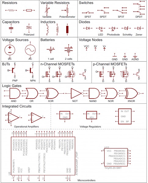
Let’s get started with a detailed look at the symbols representing various components commonly found in automotive electrical systems.
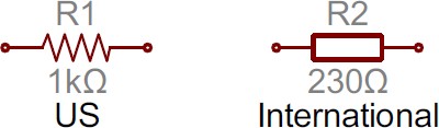
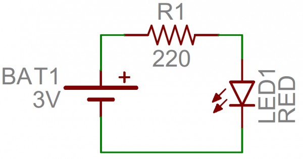
Resistors
Resistors are fundamental components used to control current flow in circuits. In wire diagrams, resistors are typically represented by a zig-zag line with two terminals extending outwards. Alternatively, especially in diagrams adhering to international standards, you might see a simple rectangle used to symbolize a resistor.
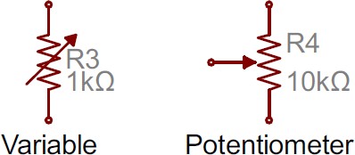
Variable Resistors and Potentiometers
In automotive applications, variable resistors and potentiometers are crucial for systems like sensor inputs or adjustable controls. These are represented by the standard resistor symbol with an added arrow. For a variable resistor (two terminals), the arrow is shown diagonally across the zig-zag. A potentiometer (three terminals), often used in volume controls or position sensors, uses the arrow as the third terminal, known as the wiper.
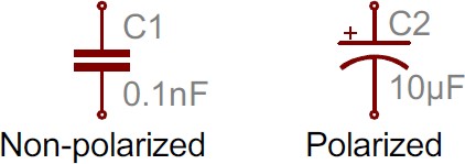
Capacitors
Capacitors, essential for filtering and energy storage in automotive electronics, have two primary symbols. One symbol is for polarized capacitors (like electrolytic or tantalum types), and the other is for non-polarized capacitors. Both symbols feature two terminals connected to parallel lines or plates.
The symbol with a curved plate indicates a polarized capacitor. In these diagrams, the curved plate usually signifies the cathode, which must be at a lower voltage than the anode (positive pin). Often, a plus sign is included next to the positive pin for clarity.
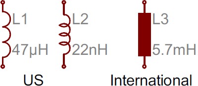
Inductors
Inductors, used in automotive circuits for filtering and in ignition systems, are typically shown as a series of curved humps or loopy coils. International standards might also represent an inductor with a filled rectangle.
Switches
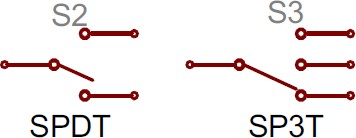
Switches are crucial for controlling various functions in a vehicle, from lights to power windows. The most basic switch, a single-pole/single-throw (SPST), is depicted with two terminals and a semi-connected line representing the switch’s actuator.
Switches with multiple throws, such as SPDT (single-pole, double-throw) and SP3T (single-pole, triple-throw), which you might find in complex automotive controls, include additional contact points for the actuator.
Multi-pole switches, like DPDT (double-pole, double-throw), often used for more complex switching circuits, are shown as multiple identical switch symbols linked by a dotted line across their actuators.
Power Sources
Automotive systems utilize various power sources, from batteries to alternators. Wire diagrams use a range of symbols to specify these power sources.
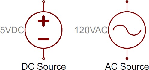
DC and AC Voltage Sources
In automotive electronics, direct current (DC) voltage sources (like batteries) are predominant. However, alternating current (AC) sources (from alternators before rectification) also play a role. These are distinguished using specific symbols:
Batteries
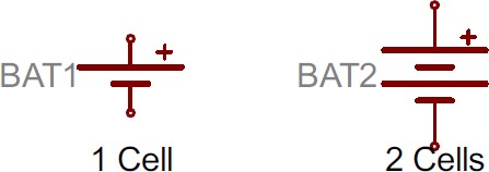
Batteries, the primary DC power source in vehicles, are symbolized by pairs of unequal length parallel lines.
Multiple pairs of these lines indicate multiple cells in series within the battery. The longer line typically represents the positive terminal, and the shorter line the negative terminal.
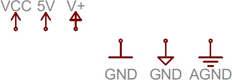
Voltage Nodes
In complex wire diagrams, especially in modern vehicles, voltage nodes are used to simplify connections. These single-terminal symbols represent direct connections to specific voltage levels like 12V, 5V, or Ground (GND). Positive voltage nodes often use an upward-pointing arrow, while ground nodes are represented by one to three flat lines, or sometimes a downward-pointing arrow or triangle.
Part 2: Advanced Wire Diagram Symbols for Auto Technicians
Building on the basics, let’s explore more complex symbols essential for understanding advanced automotive electrical systems.
Diodes
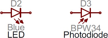
Diodes, critical for current direction control and voltage regulation in vehicles, are symbolized by a triangle pointing towards a vertical line. Diodes are polarized, with distinct symbols for the anode (positive) and cathode (negative) terminals. The anode connects to the flat edge of the triangle, and the cathode extends from the vertical line.
Various types of diodes exist, each with a modified symbol. Light-emitting diodes (LEDs), commonly used in vehicle lighting, add two small arrows pointing away from the standard diode symbol. Photodiodes, which detect light, reverse the arrows, pointing them towards the diode symbol.
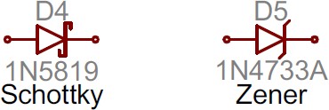
Specialized diodes like Schottky diodes or Zener diodes, used in specific automotive circuits, have their own symbols with slight variations on the vertical line part of the standard diode symbol.
Transistors
Transistors are semiconductor devices used for switching and amplification in electronic circuits. Whether they are BJTs or MOSFETs, transistors come in two main configurations: N-type and P-type.
Bipolar Junction Transistors (BJTs)
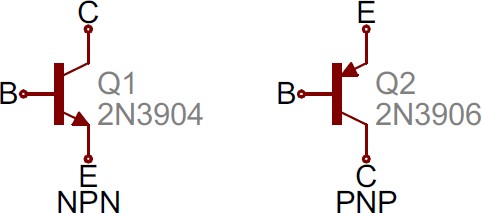
BJTs are three-terminal devices: Collector (C), Emitter (E), and Base (B). Automotive wire diagrams distinguish between NPN and PNP BJTs with unique symbols.
The collector and emitter are in line, but the emitter always has an arrow. An inward arrow indicates a PNP transistor, while an outward arrow signifies an NPN transistor. Remember: “NPN: Not Pointing In.”
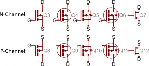
Metal Oxide Field-Effect Transistors (MOSFETs)
MOSFETs also have three terminals: Source (S), Drain (D), and Gate (G). Similar to BJTs, MOSFET symbols vary based on whether they are n-channel or p-channel types. Several symbols are commonly used for each type.
The arrow in the middle (bulk) determines the channel type. An arrow pointing in means n-channel, and pointing out means p-channel. Remember: “n is in.”
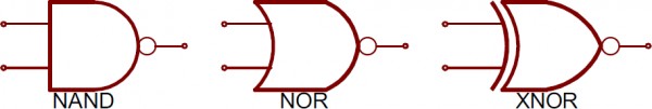
Digital Logic Gates
Logic gates are fundamental to digital electronics in vehicles, such as in engine control units (ECUs). Common logic functions like AND, OR, NOT, and XOR each have specific symbols.
Adding a small circle or “bubble” at the output of a logic gate symbol negates its function, creating NAND, NOR, and XNOR gates.
Logic gates can have multiple inputs but always have a single output.
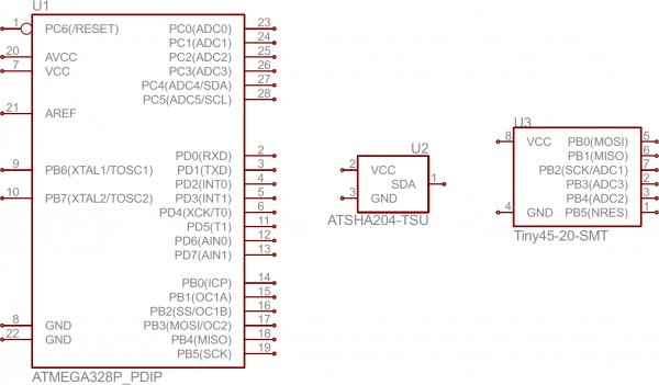
Integrated Circuits (ICs)
Integrated circuits (ICs) perform a vast array of functions in modern vehicles. Due to their complexity and variety, ICs are generally represented by a simple rectangle with pins extending from its sides. Each pin is labeled with a number and its function.
Wire diagram symbols for an ATmega328 microcontroller, an ATSHA204 encryption IC, and an ATtiny45 MCU. Notice the variation in size and pin count.
Because the IC symbol is generic, the component name and value are crucial for identification. Each IC should have a value that precisely names the chip.
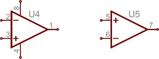
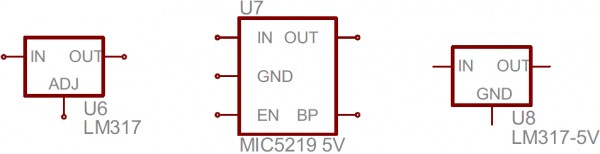
Specialized ICs: Op-Amps and Voltage Regulators
Certain common ICs have more specific symbols. Operational amplifiers (op-amps) are often shown with a distinctive symbol featuring five terminals: a non-inverting input (+), an inverting input (-), an output, and two power inputs.
Often, dual op-amps are packaged in a single IC, sharing power and ground pins, which can simplify the symbol to just three pins in some representations.
Voltage regulators, essential for maintaining stable voltage levels, are typically represented as three-terminal devices with input, output, and ground (or adjust) pins. The symbol is usually a rectangle with input on the left, output on the right, and ground/adjust at the bottom.
Miscellaneous Symbols
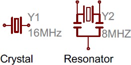
Crystals and Resonators
Crystals and resonators are vital for providing clock signals in vehicle electronics, particularly in microcontrollers. Crystal symbols usually have two terminals, while resonators, which include integrated capacitors, typically have three terminals.
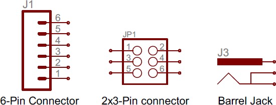
Connectors and Headers
Connectors are essential for modularity and ease of assembly in automotive wiring. Symbols vary depending on the connector type. Here are a few examples:
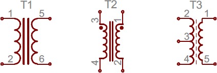
Motors, Transformers, Speakers, and Relays
These components often involve coils and are grouped together. Transformers, used for stepping up or down voltage, are represented by two coils placed side-by-side, often separated by parallel lines.
Relays, crucial for switching high-current circuits with a low-current signal, combine a coil symbol with a switch symbol.
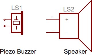
Speakers and buzzers, used for audible signals, are symbolized to resemble their physical form.
Motors, essential for various vehicle systems, are generally represented by a circle with an “M” inside.
Fuses and PTCs
Fuses and PTC (Positive Temperature Coefficient) resistors are protection devices used to limit current surges. Each has a unique symbol.
The PTC symbol is also the generic symbol for a thermistor, a temperature-sensitive resistor (note the inclusion of the international resistor symbol within it).
This guide covers the vast majority of wire diagram symbols you’ll encounter. Remember, symbols often visually resemble the components they represent. Besides symbols, each component in a diagram should have a unique name and value, further aiding identification.
Understanding Component Names and Values in Wire Diagrams
Recognizing components in wire diagrams is greatly enhanced by understanding component names and values, which complement the symbols.
Names and Values
Values specify the characteristics of a component. For resistors, capacitors, and inductors, the value indicates ohms, farads, or henries, respectively. For ICs, the value is often the chip’s part number. Crystals may list their oscillation frequency as their value. Essentially, the value highlights the key specification of the component.
Names are typically a combination of letters and numbers. The letter prefix indicates the component type—’R’ for resistors, ‘C’ for capacitors, ‘U’ for ICs, and so on. Each component in a diagram should have a unique name (R1, R2, C1, C2, etc.), which helps in referencing specific components within the diagram.
Standard prefixes are generally used for component names. For example, ‘R’ is for resistors, ‘C’ for capacitors, and ‘L’ for inductors (L for inductance). Here’s a table of common component prefixes:
| Name Identifier | Component |
|---|---|
| R | Resistors |
| C | Capacitors |
| L | Inductors |
| S | Switches |
| D | Diodes |
| Q | Transistors |
| U | Integrated Circuits |
| Y | Crystals/Oscillators |
While these prefixes are standardized, variations can occur. For instance, ICs might be prefixed with ‘IC’ instead of ‘U’, or crystals as ‘XTAL’ instead of ‘Y’. Context and symbol recognition are key to accurate identification.
Reading Automotive Wire Diagrams Effectively
Identifying components is only the first step. The next crucial skill is understanding how these components are interconnected within the diagram.
Nets, Nodes, and Labels
Nets in wire diagrams show how components are electrically connected. They are represented by lines linking component terminals. Sometimes, nets are color-coded for easier tracing, as seen in some advanced diagrams.
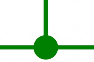
Junctions and Nodes
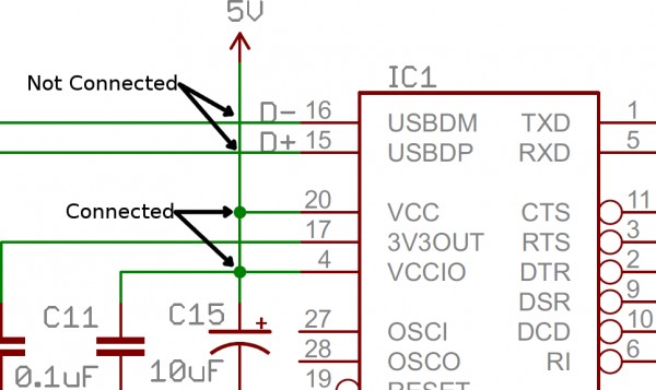
When wires intersect and connect, it’s called a junction. In diagrams, junctions are marked with nodes, small dots at the intersection points.
Nodes indicate that wires crossing at that point are electrically connected. If a junction lacks a node, it means the wires are crossing but not connected, just passing over each other. While avoiding non-connected overlaps is good practice in diagram design, they sometimes occur.
Net Names and Labels
To improve readability, especially in complex diagrams, nets are often labeled with names instead of being fully drawn across the diagram. Nets with the same name are considered connected, even without a visible connecting line. Names can be placed directly on the net line or as tags branching off the wire.
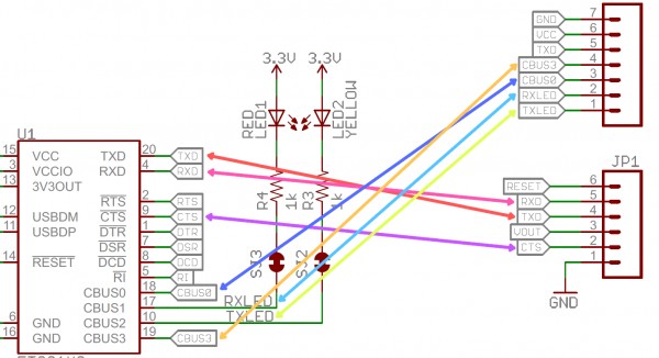
Nets with identical names are interconnected, as illustrated in this schematic for an FT231X Breakout Board. Net names and labels are crucial for managing complexity and preventing overly cluttered diagrams.
Net names usually describe the signal or voltage carried, such as “Battery_Power,” “Ground,” “Ignition_Switch,” etc.
Tips for Efficient Wire Diagram Reading
Identify Functional Blocks
Complex automotive wire diagrams are often organized into functional blocks. Sections might be dedicated to power distribution, engine controls, lighting, or infotainment. Try to identify these blocks and understand the circuit flow from input to output within each section. Well-designed diagrams often lay out circuits logically, from input on the left to output on the right.
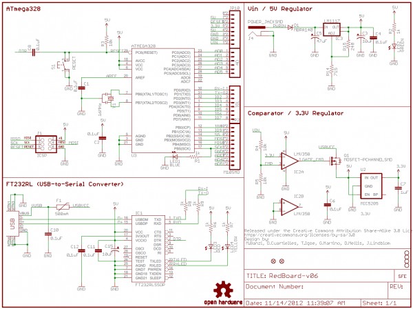
Well-structured wire diagrams, like this schematic for the RedBoard, may divide sections into labeled, logical blocks for easier understanding.
Recognize Voltage Nodes
Voltage nodes simplify diagrams by representing common voltage connections. Components connected to a voltage node are effectively connected to that voltage level, simplifying tracing and understanding power distribution.
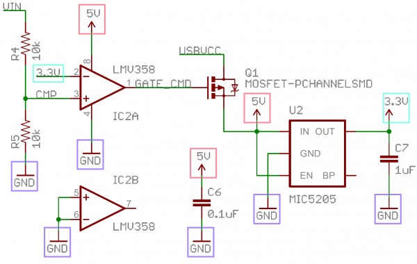
Voltage nodes like GND (Ground), +12V (Battery Voltage), and +5V (Sensor Voltage) are interconnected across the diagram, even without direct wire connections.
Ground nodes are particularly useful, as many components require a ground connection.
Consult Component Datasheets
When faced with unfamiliar components or circuit configurations in a diagram, refer to the datasheet of the key component, especially ICs like microcontrollers or sensors. Datasheets provide detailed information about component functionality and pin configurations, which can clarify diagram ambiguities.
Enhance Your Automotive Electrical Expertise
Mastering wire diagram symbols is a critical skill for any automotive technician aiming to diagnose and repair modern vehicles efficiently. By understanding these symbols and diagram conventions, you gain the ability to navigate complex automotive electrical systems effectively.
Further Resources and Practice
Ready to put your wire diagram reading skills to the test? Explore these resources to further enhance your knowledge and practice:
By continuing to learn and practice, you’ll solidify your expertise in reading wire diagrams, becoming a more skilled and efficient automotive technician.