Relays are fundamental components in a vast array of electrical and control systems, acting as electrically operated switches. Their basic function – using a small current to control a larger current – makes them indispensable in automation, automotive electronics, and industrial applications. To effectively troubleshoot or design electrical circuits, especially in vehicles, understanding relay symbols in wiring diagrams is essential.
This guide will break down the anatomy of relays, decipher the symbols used in wiring diagrams, and explain how to interpret them in practical scenarios. Whether you’re an automotive technician at keyfobprog.com or an enthusiast delving into car electronics, mastering relay symbols is a crucial skill.
The Anatomy of an Electromagnetic Relay: Coils and Contacts
At its core, an electromagnetic relay operates using two main parts: the coil and the contacts. When an electrical current flows through the coil, it generates a magnetic field. This magnetic field, in turn, causes the contacts to either close or open, thereby controlling the flow of current in another part of the circuit.
The Coil: The coil is essentially an electromagnet. It’s characterized primarily by its supply voltage. Applying the correct voltage (either DC or AC, depending on the relay type) energizes the coil and activates the relay. Common coil voltages include:
- 12 VDC
- 24 VDC
- 120 VAC
- 230 VAC
The Contacts: Contacts are the switching elements of the relay. They are defined by their state when the relay coil is de-energized (at rest) and energized (activated). There are three primary types of contacts:
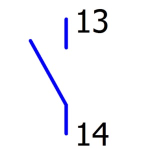
- NO (Normally Open): An NO contact is open (no current flow) when the coil is de-energized. When the coil is energized, the contact closes, allowing current to flow.
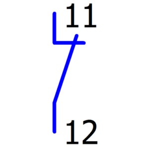
- NC (Normally Closed): An NC contact is closed (current flow allowed) when the coil is de-energized. When the coil is energized, the contact opens, interrupting the current flow.
- NCNO or C/O (Changeover): Also known as single pole double throw (SPDT), these contacts are a combination of NC and NO. They provide a common terminal that switches between a normally closed and a normally open path when the relay is energized.
Understanding these basic components is the first step to interpreting relay symbols in wiring diagrams.
Decoding Relay Symbols in Electrical Schematics
Wiring diagrams use standardized symbols to represent electrical components, and relays are no exception. The relay symbol is composed of two distinct parts: the coil symbol and the contact symbols. A single relay will always have one coil, but it can have multiple contacts, depending on its design and function. Relays can be categorized by the number of poles, which refers to the number of independent circuits the relay can switch:
- Single-pole relays: Switch one circuit.
- Two-pole relays: Switch two circuits simultaneously.
- Four-pole relays: Switch four circuits simultaneously.
Let’s examine the symbols used in wiring diagrams to represent relays and their components:
| SYMBOL | DESCRIPTION |
|---|---|
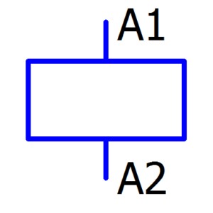
| Relay Coil: This symbol represents the coil of the relay. It’s a simple representation of the inductive component that creates the magnetic field when energized. | |
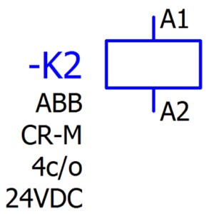
| Relay Coil with Identifier: This symbol depicts the relay coil with an identification tag, such as “-K2”. The identifier is crucial for referencing the coil and its associated contacts throughout the wiring diagram. Unique IDs are essential; no two coils in the same schematic should share the same identifier. Sometimes, additional information like the relay’s function, model, or coil voltage might be noted beneath the ID. | |
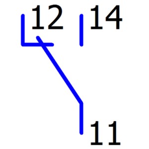
| NCNO (Changeover) Contact Symbol: This symbol represents a changeover contact. If the contact symbol is located near the coil symbol on the same diagram page and horizontal line, it might not always include the relay ID, as its association with the coil is implied by proximity. | |
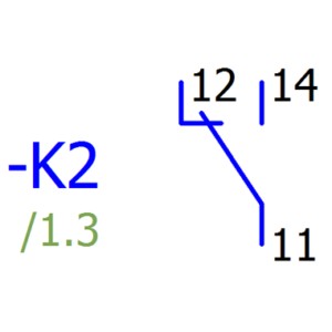
| NCNO Contact Symbol with Identifier and Location Index: When a contact symbol is placed away from its coil symbol – either on a different part of the page or on a separate page entirely – it will include the relay’s ID (e.g., “-K2”) for clear identification. Additionally, a location index (e.g., “/1.3”) might be included below the ID, indicating the page and column where the corresponding coil symbol can be found. This is vital for tracing connections across complex diagrams. | |
| Four-Pole Changeover Relay Symbol: This symbol represents a complete four-pole changeover relay, integrating both the coil and all four sets of changeover contacts into a single, comprehensive symbol. This compact representation simplifies diagrams where multi-pole relays are used. | |
| NC (Normally Closed) Contact Symbol: This symbol specifically denotes a normally closed contact. It indicates a contact that is closed in the relay’s de-energized state and opens when the relay is activated. | |
| NO (Normally Open) Contact Symbol: This symbol represents a normally open contact. It signifies a contact that is open in the relay’s de-energized state and closes to complete the circuit when the relay is energized. |
Reading Relays in Wiring Diagrams: Understanding “Normal” State
The terms “normally open” and “normally closed” refer to the default state of the contacts when the relay coil is de-energized, meaning no power is applied to the coil. Wiring diagrams are always drawn to represent the circuit in its de-energized state, before any actions are taken in the control system. This convention ensures a clear and consistent baseline for understanding circuit operation.
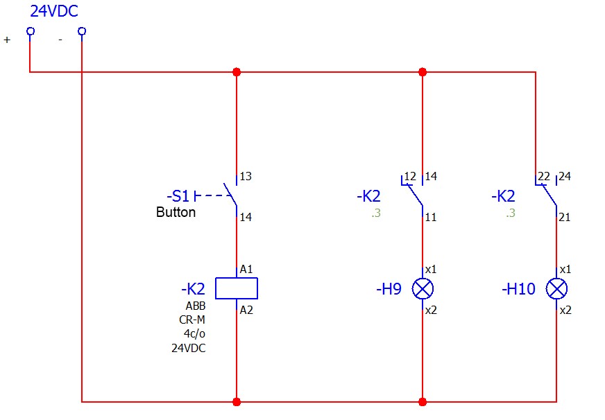
Consider this example circuit:
Diagram 1. Demonstration of NC and NO contact operation
In Diagram 1, we see a relay -K2 with both normally open (NO) and normally closed (NC) contacts. Let’s analyze the circuit behavior in different states:
Initial State (Power Applied, Button -S1 Not Pressed):
- Relay Coil -K2: No current flows through the coil because button -S1 is open. The relay is de-energized.
- Contacts 11, 12, 14 (NO): Contact 11 and 12 are connected as NC in the diagram initially, but since we are considering contacts 11, 12, 14 as a set of NO contact, initially 11 and 12 are connected, and 11 and 14 are open. However, in a normally open configuration (11, 14), contacts 11 and 14 are open, so lamp -H9 is off. (Correction: The diagram appears to mislabel the terminals for the NO contact set. In a standard NO contact, terminals would typically be labeled common, NO, and NC, and in the de-energized state, common to NO would be open and common to NC would be closed. Diagram appears to use 11, 12, 14 where 11 is common, 12 is NC, 14 is NO. For clarity in explanation, we will assume 11-14 is the intended NO contact pair).
- Contacts 21, 22, 24 (NC): Contact 21 and 22 are closed (normally closed state), so lamp -H10 receives power and is on.
Activated State (Button -S1 Pressed):
- Relay Coil -K2: Pressing button -S1 completes the circuit, energizing relay coil -K2.
- Contacts 11, 12, 14 (NO): The relay energizes, causing the NO contacts to close. Now, contact 11 and 14 become connected (assuming 11-14 as NO), providing power to lamp -H9, and it turns on.
- Contacts 21, 22, 24 (NC): The relay energizing causes the NC contacts to open. Contact 21 and 22 are now disconnected, interrupting power to lamp -H10, and it turns off.
This example clearly illustrates how relay contacts change state upon coil energization, controlling different parts of the circuit. The “normal” state is crucial for understanding the circuit’s behavior before any activation occurs.
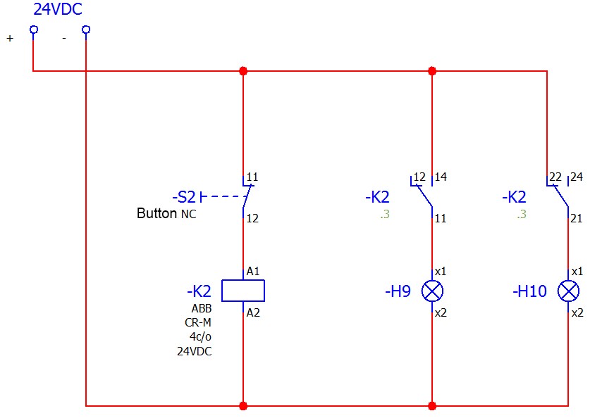
Let’s consider another scenario using a normally closed button -S2:
In this diagram, with a normally closed button -S2, the behavior is reversed. Initially, with power applied but before -S2 is pressed, relay -K2 is energized because the circuit through -S2 is initially closed. This means lamp -H9 (connected to NO contacts) is on, and lamp -H10 (connected to NC contacts) is off. Pressing -S2 opens the circuit, de-energizing relay -K2, which then causes -H9 to turn off and -H10 to turn on.
Relays in Automotive Wiring Diagrams: Key to Vehicle Electronics
For those working on vehicles, especially at keyfobprog.com, understanding relays is paramount. Modern vehicles are packed with relays controlling everything from headlights and windshield wipers to fuel pumps and starter motors. Automotive wiring diagrams heavily rely on relay symbols to represent these control circuits. Being able to quickly identify and interpret these symbols is crucial for diagnosing electrical issues and performing repairs efficiently.
Relays in automotive systems often protect sensitive electronic components by isolating them from high current loads. They also enable control of multiple circuits from a single switch, simplifying wiring and improving reliability.
Conclusion: Mastering Relay Symbols for Circuit Comprehension
Understanding wiring diagram symbols for relays is a fundamental skill for anyone working with electrical systems, especially in automotive repair. By recognizing the symbols for relay coils and different contact types (NO, NC, NCNO), and by understanding the concept of “normal” state, you can effectively interpret wiring diagrams and troubleshoot electrical circuits. This knowledge empowers you to confidently diagnose and repair electrical issues, whether you’re working on industrial control systems or the intricate electronics of a modern vehicle.
