As an auto repair expert and content creator for keyfobprog.com, I understand the critical role electrical diagrams play in diagnosing and fixing vehicle issues. While schematic diagrams are fundamental for understanding circuit functionality, Wiring Diagrams Give Information About the physical layout and connections within an electrical system. This article will delve into the world of wiring diagrams, explaining what they are, how they differ from schematics, and most importantly, the crucial information they provide for anyone working with electrical systems, especially in automotive contexts.
Schematic Diagrams: Understanding the Circuit Logic
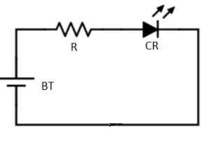
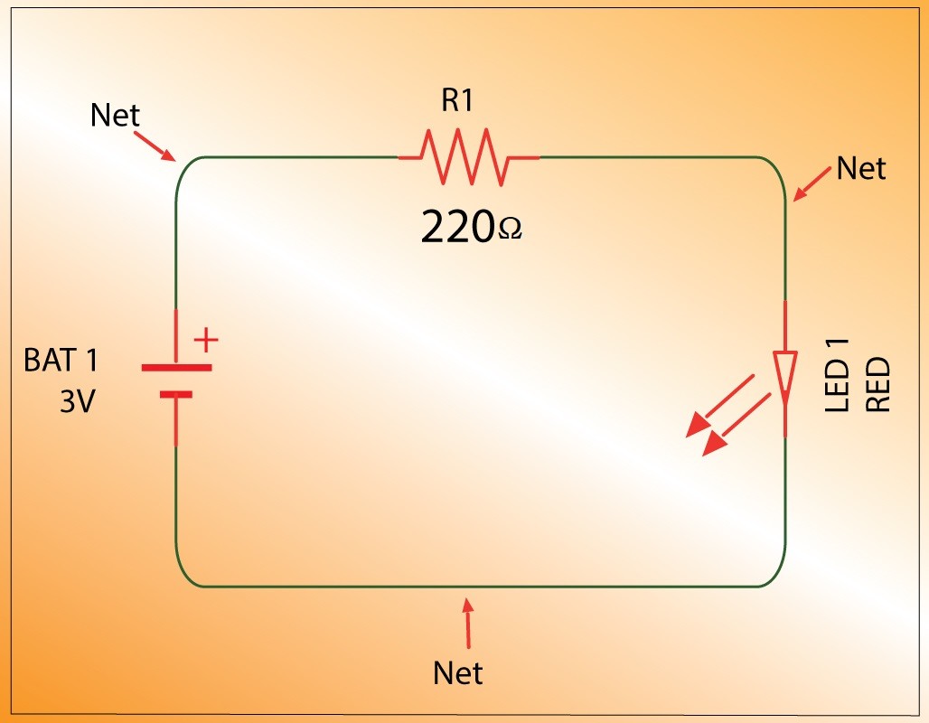
Before we focus on wiring diagrams, it’s essential to understand schematic diagrams, as they form the basis of electrical understanding. A schematic diagram is a symbolic, two-dimensional representation of an electronic circuit. It uses standardized symbols to depict components and lines to show their electrical connections.
Globally, schematic symbols adhere to standards like IEC 60617 from the International Electrotechnical Commission and ANSI standard Y32 from the American National Standards Institute. These standards ensure consistency and understanding across different regions and industries.
Schematic diagrams are crucial for understanding the functionality of a circuit. They show:
- Components used: Standard symbols represent resistors, capacitors, transistors, integrated circuits, and more.
- Electrical connections: Lines indicate the conductive paths (nets or traces) between component pins.
- Component attributes: Designations (like R1, C2, U3), values (resistance in ohms, capacitance in farads), and sometimes additional specifications like voltage or power ratings are included.
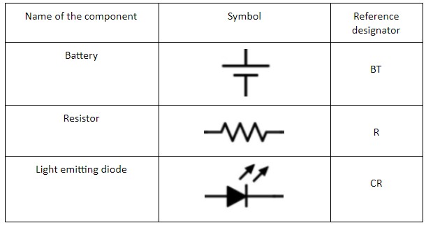
The table below highlights common schematic symbols and their reference designators:
Schematic diagrams use the International System of Units (SI) prefixes to denote component values efficiently.
| Prefix | Symbol | Value | Powers of 10 |
|---|---|---|---|
| tera | T | 1000000000000 | 1012 |
| giga | G | 1000000000 | 109 |
| mega | M | 1000000 | 106 |
| kilo | k | 1000 | 103 |
| milli | m | 0.001 | 10-3 |
| micro | u | 0.000001 | 10-6 |
| nano | n | 0.000000001 | 10-9 |
| pico | p | 0.000000000001 | 10-12 |


Wiring Diagrams: Unveiling Physical Connections and Layout
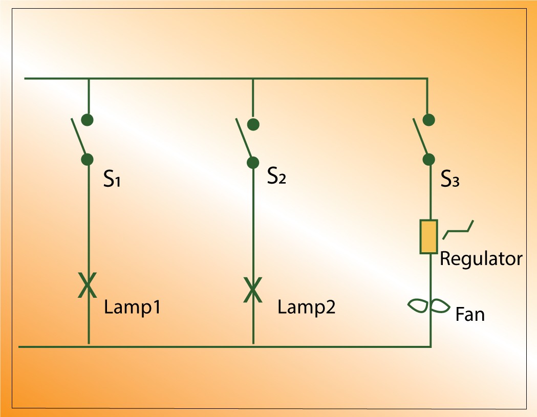
While schematic diagrams are abstract representations focusing on circuit logic, wiring diagrams give information about the physical implementation of the circuit. They are pictorial representations showing the relative positions and connections of components in a system.
Specifically, wiring diagrams give information about:
- Physical Location of Components: Wiring diagrams often depict components in their approximate physical locations within a device or system. This is crucial for assembly and troubleshooting.
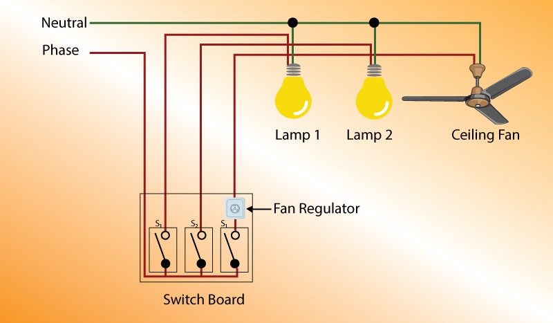
- Wire Routing and Connections: They illustrate how wires are actually routed and connected between components. This includes wire colors, connector types, and pin numbers, which are vital for hands-on work.
- Connector Details: Wiring diagrams frequently provide detailed views of connectors, showing pin layouts and wire assignments. This is essential for making correct connections and diagnosing connector-related issues.
- Harness Layouts: In complex systems like automobiles, wiring diagrams can show entire wiring harnesses, detailing how bundles of wires are organized and routed throughout the vehicle.
- Ground Points and Power Distribution: They indicate ground points, power sources, and how power is distributed throughout the system, helping to understand power flow and identify power-related problems.
For auto repair, wiring diagrams give information about tracing circuits within the vehicle’s electrical system. They are indispensable for tasks such as:
- Diagnosing electrical faults: By showing the physical path of wires, you can trace circuits to pinpoint breaks, shorts, or open circuits.
- Installing aftermarket accessories: Understanding the wiring diagram helps in safely and correctly integrating new components like alarms, lights, or audio systems.
- Repairing damaged wiring harnesses: Wiring diagrams guide you in replacing damaged sections of wiring harnesses and ensuring correct reconnection.
Reading a Wiring Diagram: Key Elements
To effectively use wiring diagrams, you need to understand their key elements:
- Component Representations: Components are often shown as simplified pictorial shapes, more closely resembling their real-world appearance than schematic symbols.
- Wires and Lines: Lines represent wires, and different line styles or colors might indicate wire gauge, type, or function (though color-coding on the diagram itself is more common).
- Connectors: Connectors are depicted with symbols or simplified drawings, often with pin numbers or labels.
- Labels and Annotations: Wiring diagrams are heavily labeled, indicating component names, wire numbers, circuit functions, and connector IDs.
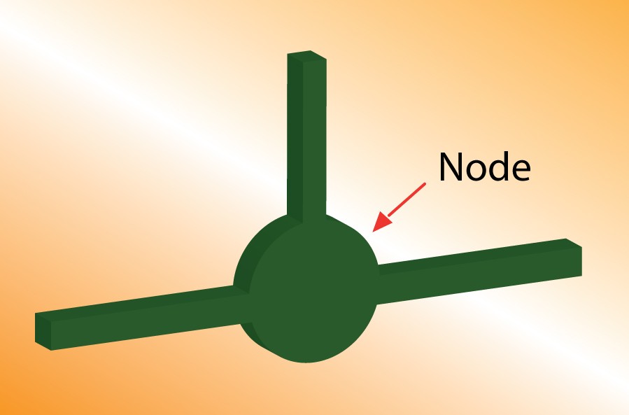
Understanding schematic nets, junctions, and nodes, as explained in the context of schematic diagrams, is also helpful when interpreting wiring diagrams, especially when they include elements of schematic representation.
Schematic Diagram vs. Layout: Logical vs. Physical
It’s important to distinguish between a schematic diagram and a PCB layout, as well as a wiring diagram.
A schematic diagram is a logical representation of connections, focusing on how components are electrically connected. It’s used in the design phase and for understanding circuit theory.
In contrast, a PCB layout and a wiring diagram show physical arrangements. A PCB layout is a precise engineering drawing showing the exact placement of components on a printed circuit board and the physical traces connecting them. A wiring diagram, while also physical, is generally less precise than a PCB layout and focuses on system-level connections rather than component-level PCB design.
Understanding PCB design tools and processes, like BOM checkers, is essential for professionals in electronics manufacturing.
Alt text: Icon for a BOM checker tool, representing software used in PCB design for Bill of Materials verification.
PCB DESIGN TOOL
BOM Checker
TRY TOOL
Creating Schematic Diagrams: A Foundation for Wiring Diagrams
Creating schematic diagrams is the first step in designing electrical systems. PCB CAD tools are used for this process, involving:
- Symbol Generation: Creating or selecting standardized symbols for components.
- Component Placement: Arranging symbols logically on the drawing.
- Pin Numbering: Ensuring correct pin assignments for connections.
- Attribute Definition: Adding component values, part numbers, and other relevant information.
Understanding schematic creation is beneficial even when primarily working with wiring diagrams, as schematics provide the underlying circuit logic that wiring diagrams implement physically.
Alt text: Icon for a DFM (Design for Manufacturing) tool, representing software used in PCB design to optimize manufacturability.
PCB DESIGN TOOL
Better DFM
TRY TOOL
Best Practices for Drawing and Interpreting Diagrams
Whether you’re drawing schematics or interpreting wiring diagrams, some best practices apply:
- Clarity and Organization: Diagrams should be clear, well-organized, and easy to follow.
- Standard Symbols: Use standardized symbols for schematics to ensure universal understanding.
- Consistent Conventions: Follow conventions like input on the left, output on the right in schematics, and logical physical layouts in wiring diagrams.
- Comprehensive Labeling: Label components, wires, nets, and connectors clearly and thoroughly.
Conclusion: Wiring Diagrams as Essential Information Sources
In conclusion, while schematic diagrams provide a crucial foundation for understanding circuit functionality, wiring diagrams give information about the real-world implementation of electrical systems. For auto repair professionals and anyone working with physical electrical systems, wiring diagrams are indispensable tools. They bridge the gap between abstract circuit theory and the tangible reality of electrical connections, enabling effective troubleshooting, repair, and installation. Mastering the ability to read and interpret wiring diagrams is a vital skill for anyone working in electronics or automotive technology.
Alt text: Banner advertisement for PCB design services, promoting professional assistance in electronic circuit board development.